13-BM-D Large Volume Press Controls
Last updated 3/15/2002
Beamline operations are split between MEDM (Motif Editor and Display Manager), the software that physically controls the beamline motors and electronics through EPICS (Experimental Physics Industrial Control System), and IDL (Interactive Data Language), the software which interacts with MEDM to save and process data. You'll need to have both packages running to collect data but only MEDM is needed to move motors, turn on and off MCA, AIM, or HV electronics, etc. We’ll start with MEDM and the MCA program, and then discuss other beamline related IDL routines. In the last section, we’ll talk about the standard procedure to start a new experiment.
1. MEDM
MEDM is an extension of EPICS and is a graphical user interface (GUI) for designing and implementing control screens, called displays, that consist of a collection of graphical objects that display and/or change the values of EPICS process variables. The supported objects include buttons, meters, sliders, text displays/entries, and graphs.
To start MEDM, click on the shortcut “MEDM” on either LeBaron or Beetle (the two PCs sitting at the 13-BM-D control area).
![]()
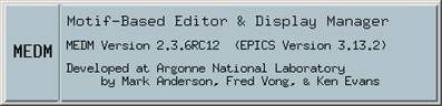
 You’ll
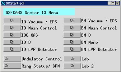
get an MEDM popup window shown on the right, together with the GSECARS Sector
13 Menu window (see left). The popup
will disappear after a few seconds.
You’ll
get an MEDM popup window shown on the right, together with the GSECARS Sector
13 Menu window (see left). The popup
will disappear after a few seconds.
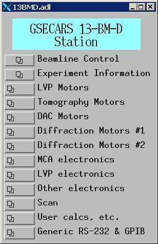
There are five buttons related to 13-BM on the GSECARS Sector 13 Menu (left). But let’s start from the third button BM D, which will bring out GSECARS 13-BM-D Station window (right below) for all controls.
Let’s go through each of the 13 items in this window. Click on the each link to find out detailed
description and functions of each item:
 1.1 Beamline
Control: beam status, equipment protection system (EPS)
status, as well as beamline slit control (in BM-A and
BM-D).
1.1 Beamline
Control: beam status, equipment protection system (EPS)
status, as well as beamline slit control (in BM-A and
BM-D).
1.2 Experiment Information: this allows you to enter specific information in a particular run (the info will be saved in the MCA file) and so the info can be saved in to each spectrum file.
1.3 LVP Motors: this is for motor controls for LVP operation.
1.4 Tomography Motors: Motor control for tomography operation – LVP will need to run the tomography CCD camera stage for the imaging setup.
1.5 DAC Motors: not used for LVP.
1.6 Diffraction Motors #1: this controls motors that drive the K/B mirrors. This is not used for white beam diffraction in the LVP; however, sometimes you may need to make sure that the K/B mirrors are not in the beam path.
1.7 Diffraction Motors #2: this is for micro diffractometer control and is not used for LVP.
1.8 MCA electronics: electronics
for the multi-channel analyzer (MCA).
1.9 LVP Electronics: this handles signals for LVP electronic devices. There is a number of electronics, such as Stanford Research Systems (SRS) preamp (# 2; used for photo diode input and output), two Keithley digital multimeters (#1 for DC signals – thermocouple, ram load and displacement, #2 used for AC signals for the power supply), and a digital-analog converter (DAC; used for controlling heating power supply).
1.10 Other electronics:
1.11 Scan: sets up scans.
1.12 User Calcs Etc:
1.13 Generic RS232 & GPIB: not used.
2. MCA: for data
acquisition. For detailed information on the CARS IDL MCA program, click here.
The MCA program now runs directly on leBaron or Beetle. On either PC, choose Start > Programs > Research Systems IDL5.5 > IDL. This will open the IDL development window (below):
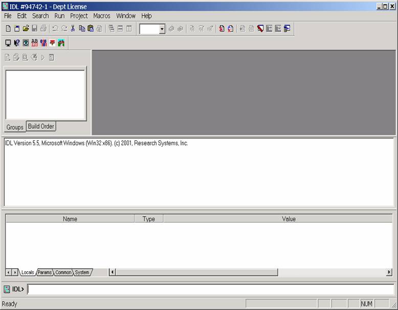
IDL version 5 displays a number of windows as part of its interface. The upper right window will show the raw code for any program that is loaded, the large window in the middle will display echos of any commands you type and any text based responses from the IDL program. The window below this will display a list of the variables that are loaded in the program and what their current values are. At the very bottom there's a command line window (next to the IDL> prompt) where you'll be typing any text based commands.
Let’s first make sure the path parameters are correctly set. First, on the above IDL development window,
choose File > Preferences > Path. Make sure the correct paths are selected as
shown on lower left.
Then choose File > Preferences > Startup and make sure that the “IDL Main directory” and “Starup file” are defined as shown in picture the middle. Also enter the correct “Working Directory”. This is the directory where you will store your data. See LVP Data Archive Structure for naming convention and storage directory definition. An alternative way to define working directory path is to type GCD in the IDL prompt (in the command field, which is the last line prefixed with IDL> in the IDL development window). You’ll be prompted to choose a directory as shown on the right: Choose the directory that you will be saving you current MCA spectra, and then click on OK.
 To get the MCA
widget running, type
MCA
in the IDL command window and hit <ENTER>. The
MCA widget will pop up as shown below.
Depending on whether you have the detector open, you may not see a
spectrum in the display window. Now you
can iconize the IDL development window, as we will no
longer need to type any command there.
To get the MCA
widget running, type
MCA
in the IDL command window and hit <ENTER>. The
MCA widget will pop up as shown below.
Depending on whether you have the detector open, you may not see a
spectrum in the display window. Now you
can iconize the IDL development window, as we will no
longer need to type any command there.
The links below give you details on the function of the MCA Display widget. Overview tells you the basics about this program; functions of the menu bars on the top of the display are given separately.
2.1 Overview
2.2 File
2.3 Controls
2.4 Displays
2.5 Data
File format
 3. CCD and Imaging
An imaging system is used to
"view" the cell under high pressure. This capability will help
greatly in finding the sample and checking thermocouple conditions under
pressure. Check with Hardware Manual for setup configuration. To view the cell,
turn CCD on and run the WinView32 program:
Start -> Program
-> WinView32
You’ll get a window that looks like
this:
4. A Suite of LVP Utilities
This
section summarizes a collection of routines (mostly in IDL) that is used for
LVP beamline operation as well as data
reduction. Click on each link to find
the details.
4.1 Logging and
Plotting Logged data
4.2 Save and Restore Motor
Positions
4.3 Convert
Data File Format from APS to SAM-85
4.4 Peak Fitting
Routines
5.
Rebooting VME Crate
6.
Experimental Startup Procedure
6.1 Create
Data File Directory on the T: drive
6.2 Copy
catch1d.env and mca.preference to That Directory
6.3 Open MEDM Control Windows
6.4
Open MCA
6.5
Turn on LVP Electronics
6.6
Turn on the Hutch Video Monitor and VCR
For suggestions/comments contact Yanbin Wang