1.11
Scan
 Click
on the scan button and drag down to Scan1
to open the scan record (right). The
concept of “scan” is quite general: Drive any positioners
(which can be a motor, a compound motor, a pseudo-motor, or anything that can
be controlled to "move") while watching any detectors (time,
intensity of the photo diode, ROIs in the MCA, or
anything that can be measured). So there
are three things to define a scan: scan region of a positioner,
signal from a detector, and detector triggers that set the criteria as to when
a scanned point is complete to move to the next. The results of the scan can be viewed
visually using scan plot.
Click
on the scan button and drag down to Scan1
to open the scan record (right). The
concept of “scan” is quite general: Drive any positioners
(which can be a motor, a compound motor, a pseudo-motor, or anything that can
be controlled to "move") while watching any detectors (time,
intensity of the photo diode, ROIs in the MCA, or
anything that can be measured). So there
are three things to define a scan: scan region of a positioner,
signal from a detector, and detector triggers that set the criteria as to when
a scanned point is complete to move to the next. The results of the scan can be viewed
visually using scan plot.
The top portion of the record on the right is for Positioners. Each positioner is given a Readback (Read) value, which tells the record where the current position is, and a Drive value, which defines the position to be driven to. These values are generally not hand-typed in, but rather are loaded. For any PV (process variable) that can be used as a positioner, there is a Scan button associated with it. Clicking on the Scan button will popup a window that will assist you to define the start, center, and end positions of a scan and load the scan parameters to the Scan Record.
 For
example, the LVP Lift Table Z is a scannable PV (see
LVP Lift Table record below). Under the
motor Z position field, there is a button labeled Scan. Click on that blue button (not on the label)
you’ll get a popup called “scanParmsCustom.adl”.
This lets you define the start (Start) and end (End) positions, number
of points to scan (#Pts) of the scan.
The bottom button in the middle also allows you to select whether you
want to use the start and end positions as relative (meaning the points are
move by the defined amounts from the current motor position, regardless whether
it is at zero right now), or absolute (meaning the positions entered represent
the “real” positions for start and end.
The button labeled AfterScan: will let you choose if you want the positioner to return to the position before the scan (PRIOR
POS), go to the center of the region scanned, or go to the start or end
positions.
For
example, the LVP Lift Table Z is a scannable PV (see
LVP Lift Table record below). Under the
motor Z position field, there is a button labeled Scan. Click on that blue button (not on the label)
you’ll get a popup called “scanParmsCustom.adl”.
This lets you define the start (Start) and end (End) positions, number
of points to scan (#Pts) of the scan.
The bottom button in the middle also allows you to select whether you
want to use the start and end positions as relative (meaning the points are
move by the defined amounts from the current motor position, regardless whether
it is at zero right now), or absolute (meaning the positions entered represent
the “real” positions for start and end.
The button labeled AfterScan: will let you choose if you want the positioner to return to the position before the scan (PRIOR
POS), go to the center of the region scanned, or go to the start or end
positions.
When the set up is complete, click the Load button in the popup window to load all the information to the scan record. You’ll see that in the Scan record the Positioner Read field is loaded with the PV vluae “13BMD:LVP:t1.ZRB”, which is the readback of the LVP Z motor position, and the Drive field is now loaded with “13BMD:LVP:t1.Z” which is the Z drive position PV.
It is a good idea to double check whether the motor name is correct in the scan record before a scan. To do so, move the mouse to the blue field of the Z motor in the LVP Lift Table record and middle click. You’ll see the name of that motor. In fact, you can actually keep the middle button depressed and move the PV to another field of another record, for example, to the Read field of the scan record. When you want to repeat the scan using the same positioner but use different scan regions, it is easier to change the numbers in the blue field in the scan record itself.
Up to 16 positioners can be driven simultaneously,
each with  a
set of defined start, center, and end positions.
a
set of defined start, center, and end positions.
The middle portion of the Scan Record defines Detector Triggers. Two
fields are defined. The first trigger
(Value set as “13BMD:scaler1.CNT”) is the scaler, which is
a 10 MHz clock. This trigger defines the
time duration at each position for the detector to collect data. Once the defined time is up, collection will
stop and the posiotner is moved to the next
point. The second trigger (value set as  “13BMD:aim_adc1Erase&Start”) is used
specifically for the MCA regions of interest (ROIs). Basically it tells the scanner to wait until
spectrum data collection is over for a prescribed time
duration (user set in the MCA), erase the MCA data from the display and start
another data collection when the positioner is moved
to the next point. Both trigger criteria
must be satisfied for the positioner to be move to
the next point for the next data collection.
Therefore, when you have the MCA turned on you should remember to set
the data collection time, even if when you are scanning some that’s not
involved with the MCA. Or you may want
to turn off the second trigger, when you are not doing ROI scans. To turn off the trigger, simply change the
value (VAL) from 1.0 to 0.0.
“13BMD:aim_adc1Erase&Start”) is used
specifically for the MCA regions of interest (ROIs). Basically it tells the scanner to wait until
spectrum data collection is over for a prescribed time
duration (user set in the MCA), erase the MCA data from the display and start
another data collection when the positioner is moved
to the next point. Both trigger criteria
must be satisfied for the positioner to be move to
the next point for the next data collection.
Therefore, when you have the MCA turned on you should remember to set
the data collection time, even if when you are scanning some that’s not
involved with the MCA. Or you may want
to turn off the second trigger, when you are not doing ROI scans. To turn off the trigger, simply change the
value (VAL) from 1.0 to 0.0.
The bottom portion of the Scan Record defined Detectors. Typical setting for the LVP is shown in the Scan Record image: Detector 01 is the photo diode, which sense X-ray intensity and convert that into current. This is not a quantitative device, and is used typically during alignment to help center the X-ray optical components on the beam. Detector 02 is the ion chamber, which is located before the sample to measure I0. For white beam diffraction, it is not used. Other detectors are most often used for ROIs in the MCA. A total of 70 detectors may be used simultaneously and the More button will display all the detectors (right). Clicking on each button in this record will display 10 detectors.
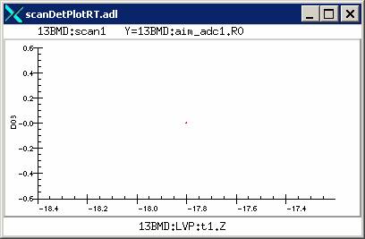
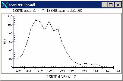 During
a scan, you may (and should) plot the scanned values on the detector side to
help you visualize the scan result. This
is done by clicking on the number button for the detector. For example, for the above Scan Record,
clicking on the button 03 will give
you two choices: plot current scan
or plot after scan. The first choice will let you view a live
plot as each positioner point is scanned through
(left); whereas the second choice after a scan will show the completed scan
result (right).
During
a scan, you may (and should) plot the scanned values on the detector side to
help you visualize the scan result. This
is done by clicking on the number button for the detector. For example, for the above Scan Record,
clicking on the button 03 will give
you two choices: plot current scan
or plot after scan. The first choice will let you view a live
plot as each positioner point is scanned through
(left); whereas the second choice after a scan will show the completed scan
result (right).
Note that some live scan plots still have bugs. For example, sometimes the last scan point from the previous scan gets plotted on the live plot, making it hard to read the scan plot. When this happens, you’ll have to view the after scan plot to help you visualize the result.