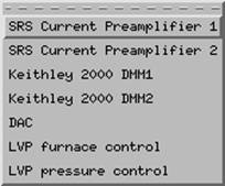
1.5 Other Electronics
This section
contains control records for the Stanford Research System’s preamplifiers (for
getting photo diode information), scaler, Keithley 2000 (for logging in analog signals such as
heating current, voltage, LVDT displacement information, oil pressure, etc.),
DAC (control signal for heating), and furnace and pressure control.
The electronics are used for various purposes.
·
SRS Current
Preamplifier 1 is not used by LVP.
·
SRS Current
preamplifier 2 is used for the magnifying the photo diode output
(beam intensity monitor),
·
Scaler for clock and photo diode readings,
·
Keithley 2000 DMM1 for logging DC signals such as LVDT,
pressure, thermocouple emf, etc. information.
·
Keithley 2000 DMM2 for logging AC signals such as voltage
and current of the AC power supply.
·
DAC for
sending control signal (0-10 VDC) to the power supply for heating. This is no
longer used directly as the control for heating.
·
LVP furnace control group (for PID
heating control), which can be found by clicking here.
·
LVP pressure control: for pressure ramping,
manual pressure increase and decrease
1.5.1. SRS current preamplifier 2 [SR570.adl]:
You can change the settings on the SRS preamps remotely by clicking these buttons. Especially, if the photo diode readings are around 640,000, it means it is saturated. You should (1) reduce the beam, and (2) change the sensitivity (e.g., from nA to microA).
1.5.2. Scaler [scaler_full.adl]:
1.5.3. Kiethley 2000 DMM1
First click on Keithely 2000 DMM1 will bring you to the following window:
Click on "More" and select "Multi-channel screen" will bring you to the following window. Remember to close the single-channel screen.
Make sure to click on the "INIT" bottom to activate the Keithley. Also make sure the "SCAN RATE" button is set at scan option (i.e., a rate is given, such as 0.1 second, 0.2 second, etc, NOT set at "EVENT" or "Passive"). Clicking on the "CALC" button next to any channel will open the calculation window (see below). You'll see that the number under "Result" gets updated every few seconds. DMM1 is used for all DC signals as shown in the above image.
1.5.4. DMM2 is for all AC signals
(volts and amps of the power supply). Note that the FUNCTION
button is set at AC. However, the Keithley has a
tendency of starting out with DC. So whenever this Keithley window is brought up fresh,
click the FUNCTION button to DC and then back to AC to be
sure that AC is really selected.
Each channel has a RAW and a CALC value. RAW is the raw input value, which can be manipulated to give a value more meaningful for the user. Click on CALC will open a calculation record. There are 12 variables with each CALC record, each with an Input link (which gives the input name of process variable) and a value (for that PV), which can be used for calculation in the Calc field. Constants can be entered under the Value column for calculation. In the example below, A is an input from thermocouple emf (Chan1_raw), B through F are fitting constants to convert emf to temperature. The expression in the Ch10_Calc field then calculates temperature.
1.5.5 DAC [DAC.adl]:
DAC controls the AC power supply by sending a DC voltage signal to the supply. The DC signal is from 0 to 10 V, corresponding to the output AC voltage from 0 to maximum (which is set up by choosing cable setups on the supply). This record is no longer used for temperature control. Click here to see furnace control information.
1.5.6 LVP Furnace Control
![]()
The LVP Furnace Control (found under Other
electronics on 13BMD.adl) directly controls the DAC (Digital to Analog
Converter) which controls the AC power supply control voltage. This control
voltage can be adjusted by either entering a value in the Control Voltage
field, or "tweaking" it with the two tweak buttons (see above). A
voltage limit can (and should) be set.
Note: you should always set a volt limit low enough to help reduce the risk
of power overshoot. However, if you
forget to raise the limit and find temperature is no longer increasing because
of this limit, DO NOT just raise volt limit, as the PID will try to shoot the
power up instantaneously based on the accumulated Proportional and Integrated
differences. When you hit the volt
limit, lower the temperature first so that you are no longer volt limited, change
the limit to a higher value and then increase the temperature.
The actual voltage produced by the power supply is a multiple of the control
voltage – 0-10 control volts corresponds to 0-Vmax of
the power supply (settings vary). The default ratio is 1:1 (see PID limits,
below)

Feedback control is available using the PID
(Proportional-Integral-Differential) system. This system can control on either
temperature or power. The Setpoint on the PID
feedback control window is set to the value you wish to control, whether power
or current. The Control PV adjusts the DAC (furnace power supply control
voltage).
The Readback PV monitors either the temperature
(13BMD:LVP_furnace_calcs.E NPP NMS) or power (13BMD:LVP_furnace_calcs.D NPP
NMS) (see furnace_calcs, below).
The limits and some of the calculations are in the PID limits window:
The AC power supply volts and current are in fields A and B, read from Kiethley #2. The resistance is calculated from these
values, and the power from the resistance. Field E is the ratio of the Control
Voltage to the power supply voltage, and is set here if other than 1:1. The
maximum valus for the power supply volts, current,
and power are fields F, G, and H, respectively and are also set here. Because
the limits are always in terms of control voltage, these fields are converted
to volts in fields I, J, and K. Finally, field P tells the PID to use the
minimum of I, J, and K, all divided by the control voltage:output voltage ratio, E.
Note: Field E is changed to match the
power supply settings, and fields F, G, and H may be user-adjusted.
The PID update window is used to transport control parameters.
Note that the upper left button (set as “Passive”) must be changed to a
certain update frequency (fro example 1 second) in order for the parameters to
be transported. When the state is set as
“Passive”, PID control will NOT be in control!!
The PID parameters (PID
feedback parameters) need to be adjusted when either changing the type of
furnace, or when changing from temperature to power control. Note that KD is
always zero or negative; the other terms are positive.
|
Controlled by |
KP |
KI |
KD |
|
Temperature |
0.001 – 0.005 |
0.5 – 1.0 |
0 |
|
Power |
.04 |
30 |
-15 |
The plot window allows the user to monitor how sell the controlled
parameter follows the setpoint. You must manually
adjust the range for both the setpoint (Control PV)
and the controlled value (Readback PV). These will be
in real units (°C or
Note: Current MEDM has a bug: after you input new display maximum and/or
display minimum, the plot will not re-scale when the “Replot”
button is pressed. There are two ways
to get around it. Either re-size the plot window by dragging it from one corner, or
kill the current plot window and re-open it.
The furnace calcs does just what its title
says. Notice that field D is the power, and E is the temperature. T is read
directly from Keithley #1 channel 10 (DMM1Ch10_calc.)
If a different type of thermocouple is used, this needs to be changed here to
the proper channel.
To summarize the limit situation:
Ultimately, the only thing that is controlled is the power supply control
voltage, which is the output of the DAC.
The DAC is the minimum of [(LVP furnace control control
voltage limit) and (PID update.P)]
PID update.P is the minimum of [(desired output)
and (PID limits.P)]
PID limits.P is the minimum of [(max volts),
(max amps´ resistance)
and sqrt(max
power´ resistance)], all
converted to control volt units by dividing by E.
So actually, this is the minimum of [(LVP furnace control control voltage limit), (max volts)/E, (max
amps´ resistance)/E, and sqrt(max
power´ resistance)/E].
The items in bold are all user controlled. If the power or temperature stops
increasing, all of these parameters must be checked and altered if necessary.
1.5.7. LVP Pressure
Control
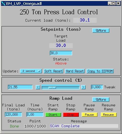
This screen is divided in three parts. The top part, Setpoints is for setting the target load. Enter the target load in the blue window directly under “Target Load”. Note that “Update” must be in seconds or fraction of seconds (typical value: 2 – 5 sec). If it is set as “passive”, then setpoint will not be in effect.
The middle part of the screen is for speed control. The maximum speed (100%) is set manually on the pressure control box mounted directly on the VME crate. If the speed on the omega controller is set at 100 (RPM), then this will be the maximum speed the pressure control can automatically reach. One can choose a lower speed by changing the percentage to less than 100%.
The lower part of the screen is for ramp control. This will let one to define a ramp speed from the current load to the next target load (called “Final Load”) is a specified number of hours. This load range will be automatically divided into 1000 equal points, and MEDM will perform a scan operation between the initial and final load to increase the load according to the time intervals defined.
Note: as a good practice, always make sure that the lower guide block is in contact with the sample (i.e., sample is already under some pressure), in order to run the ramp control.