1.3
LVP Motors
When you click on LVP Motors you’ll
get to the records which are used to control all motors the LVP: LVP Lift Table
record (simple and compound), LVP
Detector, LVP  Front Slits, CCD Camera
Stage, and Monochromator. We’ll go
through each one below.
Front Slits, CCD Camera
Stage, and Monochromator. We’ll go
through each one below.
1.3.1 LVP Lift Table Records (Simple and Compound)
The LVP Lift Table is a essentially the
“goniometer” that carries the LVP to position the sample into the diffracting
volume defined by the X-ray optics.
Let’s be reminded that the APS coordinate system (right handed) is such
that the incident X-ray direction is defined as positive Z, the vertical (up)
direction is positive Y, and the horizontal direction (pointing outwards, away
from the center of the ring) is positive X.
In the horizontal plane (defined by X and Z), the table is a kinematic
mount, with a point, a line (parallel to Z), and a plane that are accomplished
by three pairs of high-load capacity, ball- bearing slides. The two slides in each pair are perpendicular
to each other, in X and Z directions. Two motorize slides (in X and Z) defines
a point, which can change its position by moving X and/or Z. This “point” slide pair is located upstream
of the X-ray beam and in the outboard – this is the first slide assembly you’ll
see when you get into the 13-BM-D hutch.
One motor in X (and a free slide in Z) defines a line along Z. This “line” is the inboard assembly in the
hutch. And the third pair is free to
move in both X and Z and thus defines a plane.
This is the downstream assembly.
Thus the table has three motors for positioning in the horizontal
plane. When we want to move the press in
the X-direction, we need to drive the two motorized X-slides
synchronously. When we want to drive the
press in Z direction, we need to drive only one motor (the Z-slide). Rotation about the Y axis can be done by
driving the two X-slides in opposite directions; of course, Z slide also need
to change in order to keep the center of the press fixed. In addition, three vertical Duff-Norton jacks
are used to drive the press up and down.
All of the three jacks are motorized and they need to be synchronized
for Y position control. In principle,
rotations about the X and Z axes can also be done by driving the three vertical
jacks independently; but we haven’t seen the needs for that yet. Details of the table geometry is given under
geometry set up below.
bearing slides. The two slides in each pair are perpendicular
to each other, in X and Z directions. Two motorize slides (in X and Z) defines
a point, which can change its position by moving X and/or Z. This “point” slide pair is located upstream
of the X-ray beam and in the outboard – this is the first slide assembly you’ll
see when you get into the 13-BM-D hutch.
One motor in X (and a free slide in Z) defines a line along Z. This “line” is the inboard assembly in the
hutch. And the third pair is free to
move in both X and Z and thus defines a plane.
This is the downstream assembly.
Thus the table has three motors for positioning in the horizontal
plane. When we want to move the press in
the X-direction, we need to drive the two motorized X-slides
synchronously. When we want to drive the
press in Z direction, we need to drive only one motor (the Z-slide). Rotation about the Y axis can be done by
driving the two X-slides in opposite directions; of course, Z slide also need
to change in order to keep the center of the press fixed. In addition, three vertical Duff-Norton jacks
are used to drive the press up and down.
All of the three jacks are motorized and they need to be synchronized
for Y position control. In principle,
rotations about the X and Z axes can also be done by driving the three vertical
jacks independently; but we haven’t seen the needs for that yet. Details of the table geometry is given under
geometry set up below.
So the
“simple” LVP_Lift_Table record shows all the physical motors and their
positions. You'll see
several columns listed. "Motor Description" tells you which motor
you're moving, "Limits Readback" tells you at what position that
particular motor is currently sitting at. In the "Move Absolute"
field you can enter a value that you want the motor to move to. In any MEDM
screen you'll find that the mouse cursor MUST be in
that entry field in order for you to enter a value!! Once you hit the <ENTER> key the motor
will immediately move to this position. The "Tweak Jog" field
allows you to enter an increment by which you'd like to move a motor. The More Controls button for each motor allows you
to set the motor parameters such as speed, acceleration, deceleration,
backlash, etc. To drive a motor to its
new position, simply type the position (in mm) in the field under “Move
absolute”. You can also define a step
size by entering the step size (in mm) in the “Tweak Jog” field: then clicking
the right pointing arrow (“>”) will drive the motor “up” (towards positive)
by the step size specified; clicking the left pointing arrow (“<”) will
drive the motor towards negative by that step.
In this example if you enter 1.000 (again, mouse cursor
must be in the window and you have to hit <ENTER> to accept) for the
Upstream X, the motor will move by 1.000 mm every time you hit the arrow keys
on each side of the window. The left arrow key will move you -1.000 mm, the
right arrow key will move you +1.000 mm.
Don't worry about the JogR and JogF buttons, they don't really work
correctly right now. You'll also see two buttons under "Mode" labeled
"Use" and "Set." In "Use" mode numbers you
entered are taken to be positions or increments you wish to move to. By
selecting the "Set" mode you can redefine a position. For example if you click on "Set"
and then enter 10.000 in the "Move Absolute" field for the Z drive,
the motor WILL NOT move to 10.000 mm,
instead you've redefined the REAL position
13.571 to be a USER VALUE of 10.000 mm. Do not set user values for LVP Lift Table
motor positions. It's too easy to get confused
and all of a sudden be unsure about what position the motors are really at.
You'll also find some buttons in red that will issue a "Go",
"Pause", or "Stop" command...which are all useful. There is
also a button labeled "More Controls" which allows full control
of all motor parameters...for example redefining motor positions, limits, etc.
Again, unless you're 100% sure you know what you're doing do not use these
controls. And if you do use them accidentally make sure you inform us of it. Better to be a little embarrassed than not
know where things are. All the motors have this same basic GUI layout.
 In fact for LVP lift
table, you probably never need to use the simple lift table record, because it
is too hard to drive the press based on physical motors. You’d have to drive more than one motor at a
time and have to make lots of calculations on the fly to figure out where you
are going, especially when you attempt to rotate the press, or sometime (when
running the T-Cup) scan the press along an inclined line. All of these controls are much more easily
done using the Compound Lift Table Record. As a general rule,
ALWAYS USE THE COMPOUND VERSION FOR EXPERIMENTAL
CONTROL!
In fact for LVP lift
table, you probably never need to use the simple lift table record, because it
is too hard to drive the press based on physical motors. You’d have to drive more than one motor at a
time and have to make lots of calculations on the fly to figure out where you
are going, especially when you attempt to rotate the press, or sometime (when
running the T-Cup) scan the press along an inclined line. All of these controls are much more easily
done using the Compound Lift Table Record. As a general rule,
ALWAYS USE THE COMPOUND VERSION FOR EXPERIMENTAL
CONTROL!
The compound Lift Table record looks like the picture on the right.
In this record, X, Y, and Z refer to the beamline coordinate (Z: beam direction, positive toward down stream; Y: vertical and perpendicular to the beam, positive is up; X: horizontal, positive toward the user. Right handed system). Teacup X and Teacup Y are inclined at 35.2644° (the T-Cup angle). Z axis is parallel to the beamline Z. These are all compound motors, which means that the “motors” shown here are actually multiple motors who motions are linked through transformation matrix, according to the lift table geometry. So if you drive the X motor, you actually drive the two X motors in the simple lift table record simultaneously. Similarly, if you drive the Y motor, you are actually driving all three Y motors synchronously. When you drive the Teacup Y motor, you are driving five physical motors: three physical Y motors and two physical X motors, so that the press is running along a trajectory that is inclined by 35.2644° from the vertical line. You can see that user operation is dramatically simplified using the compound motors.
Again, you can set up the tweak value and drive the compound motors by
prescribed steps; you can set each compound motor position to a different user
defined value (Set), and you can set the current position values to zero
(Zero). But you should not do that for
LVP Lift Table, as this will become very confusing. All motor positions should be real positions
to allow users to check their current positions based on their previous runs. They also help us understand whether there is
any mechanical problems in the system.
The Sync button on the compound
record synchronizes the compound motor positions with simple motor positions
(however, compound X will be synchronized with only one of the two  simple motor X
positions). Init button will reset all
compound positions to zero (?). Click
"More" for geometry
description (see right).
simple motor X
positions). Init button will reset all
compound positions to zero (?). Click
"More" for geometry
description (see right).
To check geometry set up, choose "Setup (GEOCARS geometry)". Note
we are always using the GSECARS geometry. Do not go to Setup (SRI
geometry).
 On the far left is the
general coordinate setup. In our case
the local X’ and Z’ axes are parallel to the global coordinates. That is table angle is 0°. In the middle is our table set up: M0 is the
“line”, M1 is the “plane”, and M2 the
“point”. The distance between M0 and M2
is 1133.91 mm, along the X’ (X) direction, and the distance between M1 and M2
is 1282.7 mm, in the Z’ (Z) direction.
This definition implies that M2 is the origin in the local coordinate
system. The rotation center is defined
through a reference point R. In our
case, R coincides with M2 (thus Rx’=Ry’=Rz’=0).
The “Fixed” point is along the vertical axis of the press. On the table plane, it is located at (Sx’=
383.88 mm, Sz’=641.35 mm). Above the
table top (it is at the sample position), the height is Sy’=790 mm. Note that these values have certain errors,
and thus when you rotate the press, you’ll need to perform scans to recenter
the sample.
On the far left is the
general coordinate setup. In our case
the local X’ and Z’ axes are parallel to the global coordinates. That is table angle is 0°. In the middle is our table set up: M0 is the
“line”, M1 is the “plane”, and M2 the
“point”. The distance between M0 and M2
is 1133.91 mm, along the X’ (X) direction, and the distance between M1 and M2
is 1282.7 mm, in the Z’ (Z) direction.
This definition implies that M2 is the origin in the local coordinate
system. The rotation center is defined
through a reference point R. In our
case, R coincides with M2 (thus Rx’=Ry’=Rz’=0).
The “Fixed” point is along the vertical axis of the press. On the table plane, it is located at (Sx’=
383.88 mm, Sz’=641.35 mm). Above the
table top (it is at the sample position), the height is Sy’=790 mm. Note that these values have certain errors,
and thus when you rotate the press, you’ll need to perform scans to recenter
the sample.
At the bottom of the record are user defined limits. In this example, no limits are defined for X,
Y, and Z (they are all at zero)[ rotation about Y axis has limits of ±1°.
 The last item under
compound lift table record “More” button is "Setup teacup
geometry". This record sets up
coordinate transformation fro the APS system to the “Teacup” system, where X”
and Z” are rotated about the common Y (=Y”) axis by 35.2644°
(i.e., counterclockwise rotation if viewed with X-ray coming towards you). You must make sure this angle is correctly
set before running any scans in the Teacup mode. If the Teacup angle is set at 0.0° (as
shown in the example on the right), the Teacup X” and Y” axes will be parallel
to the X and Y.
The last item under
compound lift table record “More” button is "Setup teacup
geometry". This record sets up
coordinate transformation fro the APS system to the “Teacup” system, where X”
and Z” are rotated about the common Y (=Y”) axis by 35.2644°
(i.e., counterclockwise rotation if viewed with X-ray coming towards you). You must make sure this angle is correctly
set before running any scans in the Teacup mode. If the Teacup angle is set at 0.0° (as
shown in the example on the right), the Teacup X” and Y” axes will be parallel
to the X and Y.
You may press the “Define T-cup origin” button to set the Teacup X and Y
value positions for your sample to zero.
This will help you return to sample positions after any scan. This reset does not affect real positions in
global coordinates. A good practice is after you have centered the sample using
the LVP lift table (compound),
set that point as T-Cup origin, so you can scan in the T-Cup X and Y
directions.
1.3.2 LVP_Detector
 The detector support has
five degrees of freedom: three motorized translations along X, Y, and Z, and
two rotations - simple 2-theta (about the X axis), and detector Phi (about the
Y axis). The stacking sequence is the
following (from bottom up): (1) X translation, (2) Z translation, (3) Phi, (4)
Y translation, and (5) simple 2-theta.
In addition, there is a manual rotation axis (about Y) below the entire
five axis assembly. This manual rotation
is used to align the system so that it Z translation is as close to the global
Z direction as possible. After
alignment, the rotation stage is locked by two micrometer screws.
The detector support has
five degrees of freedom: three motorized translations along X, Y, and Z, and
two rotations - simple 2-theta (about the X axis), and detector Phi (about the
Y axis). The stacking sequence is the
following (from bottom up): (1) X translation, (2) Z translation, (3) Phi, (4)
Y translation, and (5) simple 2-theta.
In addition, there is a manual rotation axis (about Y) below the entire
five axis assembly. This manual rotation
is used to align the system so that it Z translation is as close to the global
Z direction as possible. After
alignment, the rotation stage is locked by two micrometer screws.
Note: Never disturb the detector support! All your 2-theta calibration will be lost if you do so.
This LVP-Detector record controls motor positions of the detector. The top five motors are simple (or real) motors, and the Compound 2-theta is a compound motor that is achieved by rotating both Two-Theta (simple 2-theta) and Detector Phi. In the DIA mode, Detector Phi must be zero (which has been set at zero at the beginning of the alignment process). For the T-Cup mode, the true 2-theta angle is decomposed into two angles, Two Theta (which is simple 2-theta) and Detector Phi. Only Compound 2-theta will give you the true 2-theta value in the T-Cup mode.
Detector Radius is not a motor; rather it is a setup parameter, which
represents the distance between the sample and the center of the detector.
 Click on the far right
button for Detector Radius, select Setup Geometry, to open the following
window: This is used to set up the LVP
Detector Geometry. Definition of the
parameters shown there are given in the record. All are in mm. Note that in
setting up the T-Cup, the angle Chi should be negative, -35.264°, not
positive as indicated in the record.
Once the geometry parameters are correctly set, you’ll be able to drive
the compound 2-theta to the desired value for your sample.
Click on the far right
button for Detector Radius, select Setup Geometry, to open the following
window: This is used to set up the LVP
Detector Geometry. Definition of the
parameters shown there are given in the record. All are in mm. Note that in
setting up the T-Cup, the angle Chi should be negative, -35.264°, not
positive as indicated in the record.
Once the geometry parameters are correctly set, you’ll be able to drive
the compound 2-theta to the desired value for your sample.
Note: A good practice for alignment is to align the incident X-ray beam with the detector first (with all the slits and collimator lined up correctly), and reset all motor positions in the LVP_Detector to zero (except for Detector Radius). Then set up the Chi angle (0 or -35.264) in the LVP Detector Geometry record. Parameters B and C should not be changed. Z0 generally also should not be changed. After all this, you can type an angle in the Compound 2-theta field, if you are running the T-Cup, to get the real 2-theta you want.
Keep in mind that the software currently has a bug, in that when you drive
the compound 2-theta at the given radius from the sample, the detector Z axis
goes positive (away from the sample).
This is why all parameters should be set at zero before driving the
compound 2-theta. To correct the Z motion error, simply type a minus sign in
front of the Z motor position in the Move Absolute field: this will reverse the
Z motor travel and put the detector on the great circle (with the given
detector radius) around the sample.
For each motor, "More Controls" gives you more information in three options
All
Gives all the information about driving this motor.
Scan Parameters button helps load scan parameters for this motor to the scan record.
Typically, use "Relative" and select "Prior Pos" so the motor will move in relative amounts and return to its position before the scan. Choose range by giving start and end points, and step size by giving number of points. Click "Load" to load the parameters to the scan record.
1.3.3 LVP Front Slits
 Before the white X-ray
beam comes into the hutch, it is collimated by two pairs of slits in 13-BMA
(the First Optics Enclosure, or FOE).
This beam is about 2x3 mm and will be used for both diffraction and
imaging (the size of the sample is typically 2 – 3 mm in height, hence the
incoming beam size. For diffraction in
the LVP, a beam cannot be more than a few hundred microns because a bigger beam
would mean lower resolution. We
generally use a beam size that is 0.1 mm (vertical width) by 0.2 mm
(horizontal). This beam size is achieved
by cutting down the incident beam using an additional pair of slits in
13-BM-D. This “Front Slit” assembly is
mounted on the upstream table that is used for DAC and tomography operations,
and consists of two motorized slides, each driving a pair of WC blades that
defines the beam width in that direction.
So using this LVP_Front_Slits record, you can drive the slit positions in
both the X and Y directions.
Before the white X-ray
beam comes into the hutch, it is collimated by two pairs of slits in 13-BMA
(the First Optics Enclosure, or FOE).
This beam is about 2x3 mm and will be used for both diffraction and
imaging (the size of the sample is typically 2 – 3 mm in height, hence the
incoming beam size. For diffraction in
the LVP, a beam cannot be more than a few hundred microns because a bigger beam
would mean lower resolution. We
generally use a beam size that is 0.1 mm (vertical width) by 0.2 mm
(horizontal). This beam size is achieved
by cutting down the incident beam using an additional pair of slits in
13-BM-D. This “Front Slit” assembly is
mounted on the upstream table that is used for DAC and tomography operations,
and consists of two motorized slides, each driving a pair of WC blades that
defines the beam width in that direction.
So using this LVP_Front_Slits record, you can drive the slit positions in
both the X and Y directions.
When switching to the imaging mode, a full, 2x3 mm beam is needed. This is accomplished by driving the front
slit assembly in X direction by about -55 to -65 mm. When the slides are completely driven out of
the way, the X-ray beam goes through the 1” thick aluminum slit holder. You may want to add more Al blocks on the
holder if the beam intensity is to strong.
1.3.4 CCD Camera Stage
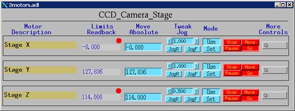 The
CCD Camera Stage is confusing here for historical reasons. This was used to drive the CCD camera in the
past in imaging experiments. Now that
tomography has set up another set of motors for CCD camera, we use that for our
imaging experiments, and we use this stage for driving the YAG phosphor assembly
that is used to convert X-ray imaging beam into visible light. This assembly contains also the 45°mirror
that reflects the visible light signal into the objectives before the CCD
camera. For this purpose only one drive
(in Y) is needed. That’s why you’ll see
that both X and Z motors are indicated to have reached their limits. The fact is they are not even connected.
The
CCD Camera Stage is confusing here for historical reasons. This was used to drive the CCD camera in the
past in imaging experiments. Now that
tomography has set up another set of motors for CCD camera, we use that for our
imaging experiments, and we use this stage for driving the YAG phosphor assembly
that is used to convert X-ray imaging beam into visible light. This assembly contains also the 45°mirror
that reflects the visible light signal into the objectives before the CCD
camera. For this purpose only one drive
(in Y) is needed. That’s why you’ll see
that both X and Z motors are indicated to have reached their limits. The fact is they are not even connected.
For the CCD camera stage, go to this link.
1.3.5 Monochromator
 The Mnochromator record is used for setting up in-hutch
monochromator. The only drive is for the
monochromator angle, which determines the energy for the mono.
The Mnochromator record is used for setting up in-hutch
monochromator. The only drive is for the
monochromator angle, which determines the energy for the mono.
For comments/suggestions please contact Yanbin Wang