Andor.adl
This is an EPICS areaDetector driver for CCD detectors from Andor Technology using Version 2 of the Andor Software Development Kit (SDK). It has been tested on the Andor iKon and DU401 CCD cameras with USB interface, but should work with other cameras as well. The driver is supported on 32-bit and 64- bit Linux and 32-bit and 64-bit Windows.
The driver currently provides access to most of the features of the Andor cameras:
The Andor module includes a separate driver to control the Andor Shamrock spectrographs. If the detector data is saved in the Princeton Instruments SPE file format using the Andor driver then it will include the Shamrock wavelength calibration information. No other file formats support saving the calibration.
This driver inherits from ADDriver. It implements many of the parameters in asynNDArrayDriver.h and in ADArrayDriver.h. It also implements a number of parameters that are specific to the Andor detectors. The Andor class documentation describes this class in detail.
This document does not attempt to explain the meaning of the Andor-specific parameters. The Andor Software Development Kit documentation provides this detailed information. Andor does not allow me to redistribute the SDK documentation as part of areaDetector. It must be obtained from Andor's Web site.
areaDetector includes the header and library files required to build the andor driver on any Linux or Windows computer. However, it does not include the shareable libraries, DLLs or drivers to actually run a detector. Those must be obtained from Andor, either by purchasing their SDK or their Solis application software. On Windows the path to the directory containing the Andor DLLs from the SDK or Solis must be added to the PATH environment variable when running the areaDetector IOC. On Linux the path to the directory containing the Andor shareable libraries from the SDK must be added to the LD_LIBRARY_PATH environment variable when running the areaDetector IOC.
NOTE: When using the Shamrock spectrograph on Windows the following DLLs must actually be copied from the SDK directory to the current working directory from which the IOC application is being run, e.g. iocBoot/iocAndor.
This is a rather strange requirement of the Andor Shamrock SDK, which will hopefully be fixed by them in a future release.
NOTE: When using SDK version >= 2.102.30000.0 on Linux one must make sure that libUSBI2C-[ARCH].so.[VERSION] is installed as part of support into libUSBI2C.so and libUSBI2C.so.2.
Also libd2xx_table.so might be needed to get Shamrock communicating. See andorSupport/ftdi_table.c for more.
Compile with:
$ gcc -fpic -shared -Wl,-soname,libd2xx_table.so -o libd2xx_table.so ftdi_table.c
Place the libd2xx_table.so into the folder with the rest of SDK support libraries.
The following table describes how the Andor driver implements some of the standard driver parameters.
| Implementation of Parameters in asynNDArrayDriver.h and ADDriver.h, and EPICS Record Definitions in ADBase.template and NDFile.template | ||
| Parameter index variable | EPICS record name | Description |
|---|---|---|
| ADTriggerMode |
$(P)$(R)TriggerMode $(P)$(R)TriggerMode_RBV |
Sets the trigger mode for the detector. Options are:
|
| ADImageMode |
$(P)$(R)ImageMode $(P)$(R)ImageMode_RBV |
Sets the image mode for the detector. Options are:
|
| ADNumExposures |
$(P)$(R)NumExposures $(P)$(R)NumExposures_RBV |
Sets the number of accumulations (performed in software in Andor's driver) in Single and Multiple modes |
| ADNumImages |
$(P)$(R)NumImages $(P)$(R)NumImages_RBV |
Sets the number of images to take in multiple (Kinetics Series) mode |
| ADAcquirePeriod |
$(P)$(R)AcquirePeriod $(P)$(R)AcquirePeriod_RBV |
Sets the time between images in Multiple (Kinetics Series) and Continuous (Run Till Abort) modes |
| ADGain |
$(P)$(R)Gain $(P)$(R)Gain_RBV |
Sets the pre-amp gain of the detector. For the Andor driver the Gain is treated
as an integer index into the supported gain table of the specific detector. The
list of supported gains for the detector gain be found by typing "asynReport 1,ANDOR"
at the IOC prompt. For example, on the iKon-M the relationship is:
|
| NDDataType |
$(P)$(R)DataType $(P)$(R)DataType_RBV |
Sets data type for reading out the detector. Allowed values are:
|
| ADTemperature |
$(P)$(R)Temperature $(P)$(R)Temperature_RBV |
Sets the setpoint temperature of the CCD (-120C to 20C) |
| ADTemperatureActual | $(P)$(R)TemperatureActual | Reads the actual temperature of the CCD |
| NDFileFormat |
$(P)$(R)FileFormat $(P)$(R)FileFormat_RBV |
Selects the file format for saving files with the Andor driver. Choices are:
|
The following table shows the relationship of ImageMode to the Andor acquisition modes, and the meaning of NumExposures and NumImages.
| Relationship of ImageMode to the Andor acquisition modes, and the meaning of NumExposures and NumImages. | ||||||
| ImageMode | NumExposures | AcquireTime | AndorAccumulatePeriod | NumImages | AcquirePeriod | Andor acquisition mode |
|---|---|---|---|---|---|---|
| Single | 1 | Sets exposure time | Not applicable | Not applicable | Not applicable | Single Scan |
| Single | >1 Sets number of accumulations per image. | Sets exposure time per accumulation | Sets accumulation period (cycle time) | Not applicable | Not applicable | Accumulate |
| Multiple | Sets number of accumulations per image | Sets exposure time per accumulation | Sets accumulation period if NumExposures > 1 | Sets number of images | Sets time between images (cycle time) | Kinetic Series |
| Continuous | Not applicable | Sets exposure time per image | Not applicable | Not applicable | Sets time between images (cycle time) | Run Till Abort |
| Fast Kinetics | Not applicable | Sets exposure time per sub-area | Not applicable | Controls number of sub-area exposures, each being followed by a vertical shift of SizeY. MinY controls the offset of the first row from the bottom of the CCD. SizeY controls the sub-area height. BinX and BinY control the horizontal and vertical binning. | Not applicable | Fast Kinetics |
The Andor driver implements the following parameters in addition to those in asynNDArrayDriver.h and ADDriver.h.
| Parameter Definitions in andorCCD.h and EPICS Record Definitions in andorCCD.template | ||||||
| Parameter index variable | asyn interface | Access | Description | drvInfo string | EPICS record name | EPICS record type |
|---|---|---|---|---|---|---|
| AndorCoolerParam | asynInt32 | R/W | Turn the CCD cooler on and off | ANDOR_COOLER |
AndorCooler AndorCooler_RBV |
bo bi |
| AndorTempStatusMessage | asynOctet | R/O | Temperature status message. | ANDOR_TEMP_STAT | AndorTempStatus_RBV | waveform |
| AndorMessage | asynOctet | R/O | Other status message. | ANDOR_MESSAGE | AndorMessage_RBV | waveform |
| AndorShutterMode | asynInt32 | R/W |
Selects the Andor shutter mode. Choices are:
|
ANDOR_SHUTTER_MODE | AndorShutterMode | mbbo |
| AndorShutterExTTL | asynInt32 | R/W |
Selects the TTL polarity of an external shutter. Choices are:
|
ANDOR_SHUTTER_EXTTL | AndorShutterExTTL | bo |
| AndorPALFileName | asynOctet | R/W | Path and Filename of pallette file (used for TIFF and BMP file colours) (255 chars max). | ANDOR_PAL_FILE_PATH | PALFilePath | waveform |
| AndorAdcSpeed | asynInt32 | R/W |
Switch between the slow (low noise) ADC and the fast ADC. Choices are:
|
ANDOR_ADC_SPEED |
AndorADCSpeed AndorADCSpeed_RBV |
mbbo mbbi |
| AndorAccumulatePeriod | asynFloat64 | R/W | Controls the period between accumulations when ImageMode=Single or Multiple and NumExposures>1. NOTE: Some Andor detectors (including the iKon) only support a single period when doing multiple accumulations in kinetic series mode. For these cameras ANDOR_ACCUMULATE_PERIOD has no effect, ACQUIRE_PERIOD determines the time between accumulations, and the time between images is 0, i.e. the next image starts as soon as the previous one is complete. | ANDOR_ACCUMULATE_PERIOD |
AndorAccumulatePeriod AndorAccumulatePeriod_RBV |
ao ai |
| AndorAccumulatePeriodActual | asynFloat64 | R/O | Reads the actual value of AndorAccumulatePeriod, which may differ from the requested value due to timing limitations of the detector. | ANDOR_ACCUMULATE_PERIOD_ACTUAL | AndorAccumulatePeriodActual | ai |
| AndorAcquireTimeActual | asynFloat64 | R/O | Reads the actual value of ADAcquireTime, which may differ from the requested value due to timing limitations of the detector. | ANDOR_ACQUIRE_TIME_ACTUAL | AndorAcquireTimeActual | ai |
| AndorAcquirePeriodActual | asynFloat64 | R/O | Reads the actual value of ADAcquirePeriod, which may differ from the requested value due to timing limitations of the detector. | ANDOR_ACQUIRE_PERIOD_ACTUAL | AndorAcquirePeriodActual | ai |
| AndorBaselineClamp | asynInt32 | R/W | Enable or disable the baseline clamp option. | ANDOR_BASELINE_CLAMP |
AndorBaselineClamp AndorBaselineClamp_RBV |
bo bi |
| AndorEMGain | asynInt32 | R/W | Controls the Electron Multiplying (EM) Gain level on supported detectors. The valid range depends on the value of AndorEMGainMode and the detector temperature. For cameras that do not support EM Gain, AndorEMGain has no effect. | ANDOR_EM_GAIN |
AndorEMGain AndorEMGain_RBV |
ao ai |
| AndorEMGainMode | asynInt32 | R/W |
Sets the EM Gain mode on supported detectors. Choices are:
|
ANDOR_EM_GAIN_MODE |
AndorEMGainMode AndorEMGainMode_RBV |
mbbo mbbi |
| AndorEMGainAdvanced | asynInt32 | R/W |
Enables access to higher EM Gain levels. Choices are:
|
ANDOR_EM_GAIN_ADVANCED |
AndorEMGainAdvanced AndorEMGainAdvanced_RBV |
bo bi |
| AndorReadOutMode | asynInt32 | R/W |
Switch between the readout modes. Choices are:
|
ANDOR_READOUT_MODE |
AndorReadOutMode AndorReadOutMode_RBV |
mbbo mbbi |
| AndorFTMode | asynInt32 | R/W |
Set Frame Transfer mode. Choices are:
|
ANDOR_FT_MODE |
AndorFTMode AndorFTMode_RBV |
bo bi |
| AndorVSPeriod | asynInt32 | R/W |
Sets Vetical Shift Period, in units of microseconds per pixel shift. Choices are constructed at runtime. For example, the choices for an iDus are:
| ANDOR_VS_PERIOD |
AndorVSPeriod AndorVSPeriod_RBV |
mbbo mbbi |
ColorMode, ReverseX, and ReverseY are currently not supported.
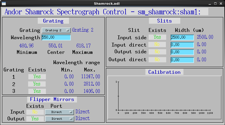
The Andor module also includes a driver for the Andor Shamrock spectrographs. This driver allows control of the grating, central wavelength, and slit sizes.
| Parameter Definitions in shamrock.cpp and EPICS Record Definitions in shamrock.template | ||||||
| Parameter index variable | asyn interface | Access | Description | drvInfo string | EPICS record name | EPICS record type |
|---|---|---|---|---|---|---|
| SRGrating | asynInt32 | R/W | Selects the grating to use | SR_GRATING |
Grating Grating_RBV |
mbbo mbbi |
| SRGratingExists | asynInt32 | R/O | Flag indicating if a grating is present | SR_GRATING_EXISTS | GratingExists[N], N=1-3 | bi |
| SRWavelength | asynFloat64 | R/W | Selects the central wavelength | SR_WAVELENGTH |
Wavelength Wavelength_RBV |
ao ai |
| SRMinWavelength | asynFloat64 | R/O | The minimum wavelength of the current configuration (ADDR=0) or the minimum wavelength of grating N (N=1-3) | SR_MIN_WAVELENGTH | MinWavelength, MinWavelength[N], N=1-3 | ai |
| SRMaxWavelength | asynFloat64 | R/O | The maximum wavelength of the current configuration or the maximum wavelength of grating N (N=1-3) | SR_MAX_WAVELENGTH | MaxWavelength, MaxWavelength[N], N=1-3 | ai |
| SRSlitSize | asynFloat64 | R/W |
The size of slit N, N=1-4. The slits are numbered as follows:
|
SR_SLIT_SIZE |
SlitSize[N], N=1-4 SlitSize[N]_RBV |
ao ai |
| SRSlitExists | asynInt32 | R/O | Flag indicating if a slit is present | SR_SLIT_EXISTS | SlitExists[N], N=1-4 | bi |
| SRCalibration | asynFloat32Array | R/O | Array containing the wavelength calibration of each X pixel of the detector in nm. | SR_CALIBRATION | Calibration | bi |
Always use channel access put callback when setting parameters.
If any of the parameters set are out of range or fail in some way, then the PV will be put into alarm state. This should be checked after every PV set.
An example palette file for a TIFF file is GREY.PAL in the iocAndor directory.
The Andor driver is created with the andorCCDConfig command, either from C/C++ or from the EPICS IOC shell.
int andorCCDConfig(const char *portName,
                int maxBuffers, size_t maxMemory,
                const char* installPath,
                int priority, int stackSize)
The Shamrock driver is created with the shamrockConfig command, either from C/C++ or from the EPICS IOC shell.
int shamrockConfig(const char *portName,
                          int shamrockId, const char *iniPath,
                          int priority, int stackSize)
For details on the meaning of the parameters to this function refer to the detailed documentation on the andorCCDConfig function in the shamrock.cpp documentation and in the documentation for the constructor for the shamrock class.
There an example IOC boot directory and startup script (iocBoot/iocAndor/st.cmd) provided with areaDetector.
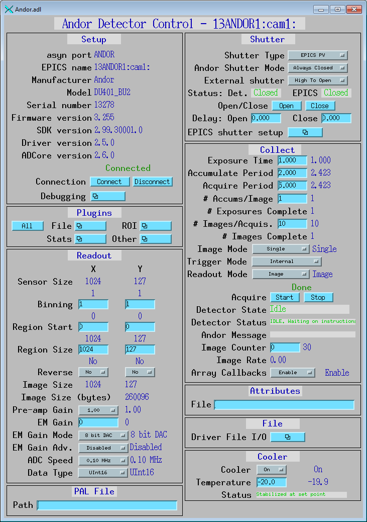
The following shows the MEDM screen that is used to control the Andor detector. Note that the general purpose screen ADBase.adl can be used, but it exposes a few controls that are not applicable to the Andor, and lacks some fields that are important for the Andor.
Andor.adl is the main screen used to control the Andor driver.
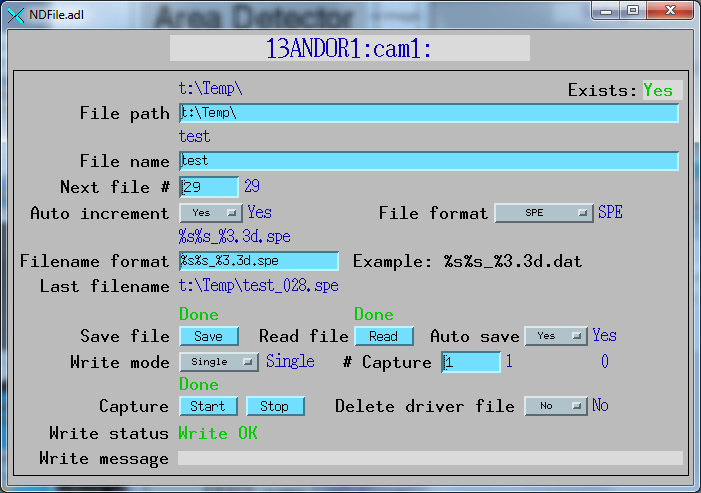
The following shows the MEDM screen that is used to save files directly with the Andor detector.
The following shows the MEDM screen that is used to control the Shamrock spectrograph.
The following are known restrictions of the Andor driver. These should be fixed in a future release.