LVP
Furnace Control
![]()
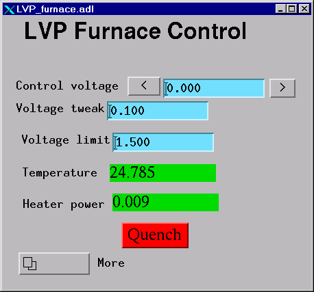
The LVP Furnace Control (found under Other electronics on 13BMD.adl) directly
controls the DAC (Digital to Analog Converter) which controls the AC power
supply control voltage. This control voltage can be adjusted by either entering
a value in the Control Voltage field, or "tweaking" it with the two
tweak buttons (see above). A voltage limit can (and should) be set.
Note: you should always set a volt limit low
enough to help reduce the risk of power overshoot. However, if you forget to raise the limit and
find temperature is no longer increasing because of this limit, DO NOT just
raise volt limit, as the PID will try to shoot the power up instantaneously based
on the accumulated Proportional and Integrated differences. When you hit the volt limit, lower the
temperature first so that you are no longer volt limited, change the limit to a
higher value and then increase the temperature.
The actual voltage produced by the power
supply is a multiple of the control voltage – 0-10 control
volts corresponds to 0-Vmax of the power supply (settings vary). The
default ratio is 1:1 (see PID limits, below)

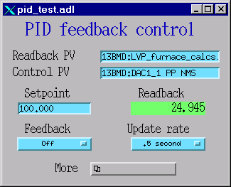
Feedback control is available using the PID
(Proportional-Integral-Differential) system. This system can control on either
temperature or power. The Setpoint on the PID
feedback control window is set to the value you wish to control, whether power
or current. The Control PV adjusts the DAC (furnace power supply control
voltage).
The Readback PV
monitors either the temperature (13BMD:LVP_furnace_calcs.E NPP NMS) or power
(13BMD:LVP_furnace_calcs.D NPP NMS) (see furnace_calcs,
below).
The limits and some of the calculations are
in the PID limits window:
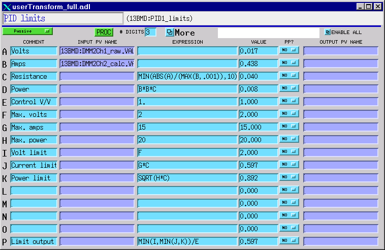
The AC power supply volts and current are in
fields A and B, read from Kiethley #2. The resistance
is calculated from these values, and the power from the resistance. Field E is
the ratio of the Control Voltage to the power supply voltage, and is set here
if other than 1:1. The maximum valus for the power
supply volts, current, and power are fields F, G, and H, respectively and are
also set here. Because the limits are always in terms of control voltage, these
fields are converted to volts in fields I, J, and K. Finally, field P tells the
PID to use the minimum of I, J, and K, all divided by the control voltage:output voltage ratio, E.
Note: Field E is changed to match the
power supply settings, and fields F, G, and H may be user-adjusted.
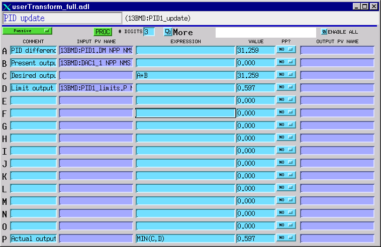
The PID update window is used to
transport control parameters.
Note that the upper left button (set as “Passive”)
must be changed to a certain update frequency (fro example 1 second) in order
for the parameters to be transported.
When the state is set as “Passive”, PID control will NOT be in control!!
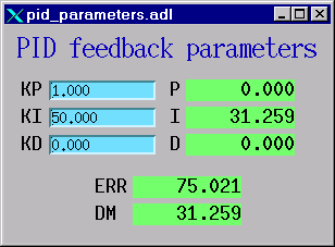
The PID parameters (PID feedback
parameters) need to be adjusted when either changing the type of furnace, or
when changing from temperature to power control. Note that KD is always zero or
negative; the other terms are positive.
|
Controlled by |
KP |
KI |
KD |
|
Temperature |
0.001 – 0.005 |
0.5 – 1.0 |
0 |
|
Power |
.04 |
30 |
-15 |
The plot window allows the user to
monitor how sell the controlled parameter follows the setpoint.
You must manually adjust the range for both the setpoint
(Control PV) and the controlled value (Readback PV).
These will be in real units (°C or Watts). When the ranges are changed, press replot to reset the scales.
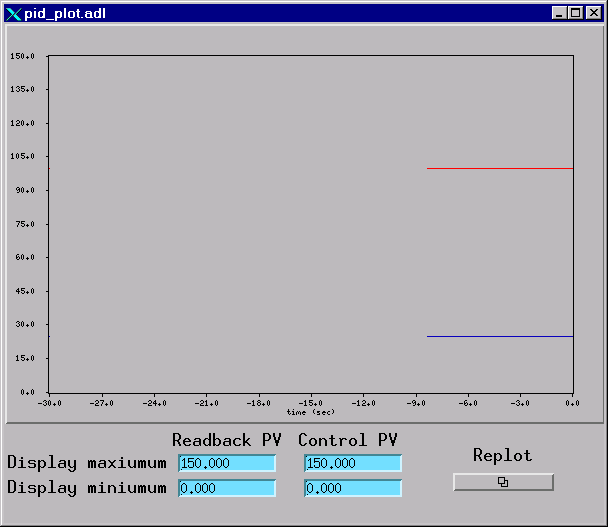
Note: Current MEDM has a bug: after you input
new display maximum and/or display minimum, the plot will not re-scale when the
“Replot” button is pressed. There are two ways to get around it. Either re-size the
plot window by dragging it from one corner, or kill the current plot window and
re-open it.
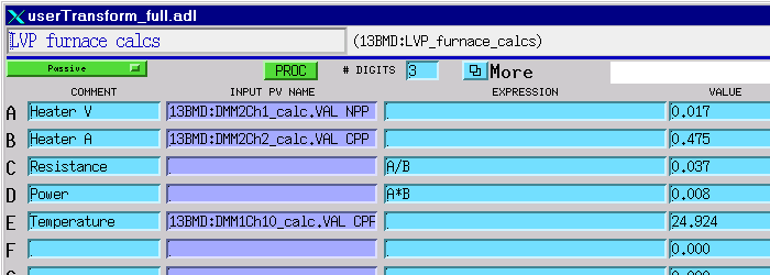
The furnace calcs
does just what its title says. Notice that field D is the power, and E is the
temperature. T is read directly from Keithley #1
channel 10 (DMM1Ch10_calc.) If a different type of thermocouple is used, this
needs to be changed here to the proper channel.
To summarize the limit situation:
Ultimately, the only thing that is controlled
is the power supply control voltage, which is the output of the DAC.
The DAC is the minimum of [(LVP furnace
control control voltage limit) and (PID update.P)]
PID update.P is the
minimum of [(desired output) and (PID limits.P)]
PID limits.P is the
minimum of [(max volts), (max amps´ resistance)
and sqrt(max
power´ resistance)],
all converted to control volt units by dividing by E.
So actually, this is the minimum of [(LVP
furnace control control voltage limit), (max
volts)/E, (max amps´ resistance)/E, and sqrt(max power´ resistance)/E].
The items in bold are all user controlled. If
the power or temperature stops increasing, all of these parameters must be
checked and altered if necessary.