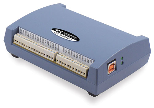
Photo of USB-1608GX-2AO
This is an EPICS driver for the multi-function devices from Measurement Computing These multi-function devices support support analog in, thermocouple in, analog out, binary I/O, counters, and timers. Not all devices have all of these capabilities. The driver is written in C++, and consists of a class that inherits from asynPortDriver, which is part of the EPICS asyn module.
The driver is written to be general, so that it can be used with any Measurement Computing multi-function module. It uses the introspection capabilities of their UL library to query many of the device features. However, there are some features that cannot be queried, so the driver does require small modifications to be be used with a new model. The models that the driver currently supports are:
This module costs $799 and has the following features:
More information can be found in the USB-1608GX-2AO product description.
The USB-1608G is very similar to the USB-1608GX-2AO except that it does not have any analog outputs and the analog inputs are limited to 250 kHz rather than 500 kHz. More information can be found in the USB-1608G product description.
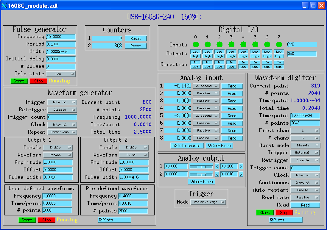
The following is the main medm screen for controlling the USB-1608GX-2AO.
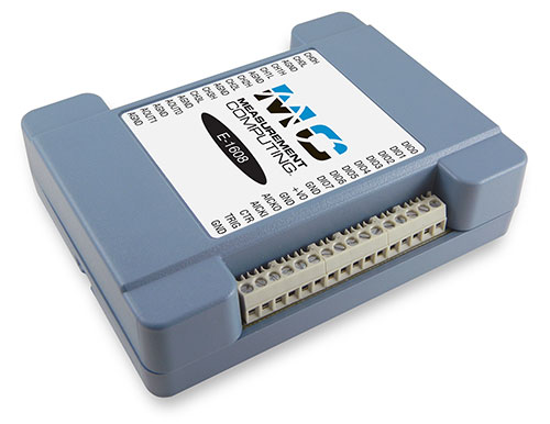
This module costs $525 and has the following features:
More information can be found in the E-1608 product description.
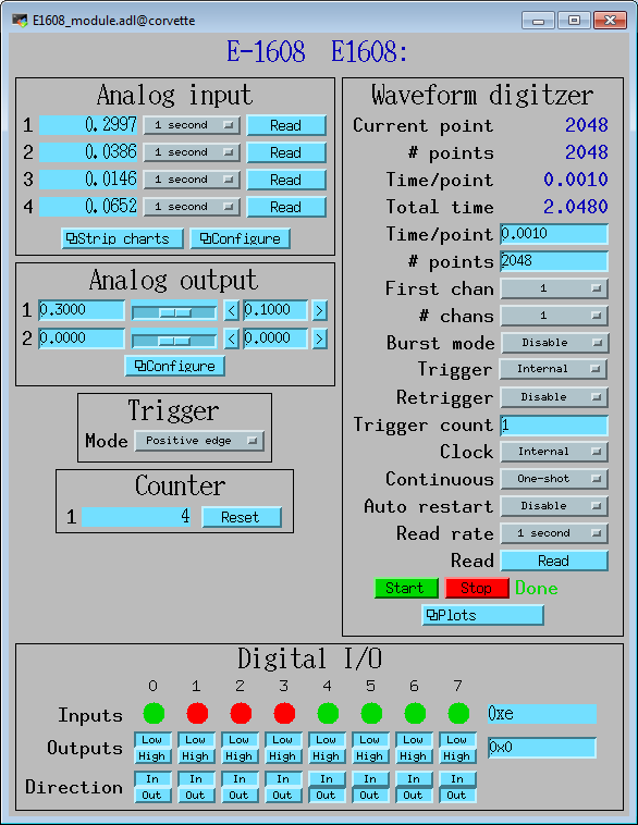
The following is the main medm screen for controlling the E-1608.

This module costs $699 and has the following features:
More information can be found in the USB-2408-2AO product description.
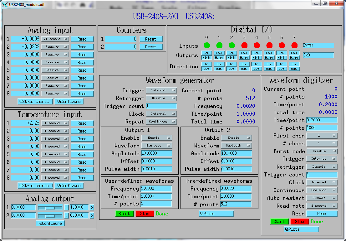
The following is the main medm screen for controlling the USB-2408-2AO.
This module costs $505 and has the following features:
More information can be found in the E-TC product description.
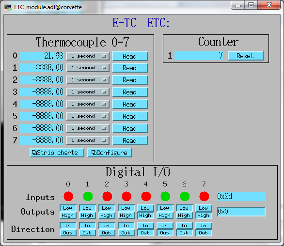
The following is the main medm screen for controlling the E-TC.
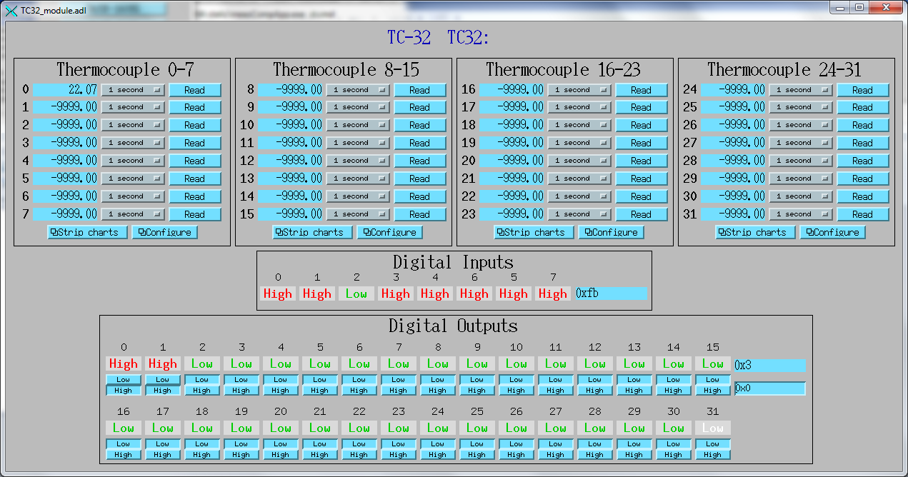
This module costs $1999 and has the following features:
More information can be found in the TC-32 product description.
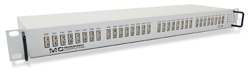
The following is the main medm screen for controlling the TC-32.
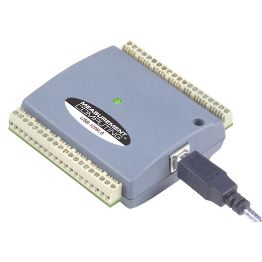
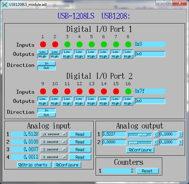
This module costs $129 and has the following features:
More information can be found in the USB-1208LS product description.
The USB-1208HS and USB-231 are similar devices but with higher performance.
The following is the main medm screen for controlling the USB-1208LS.
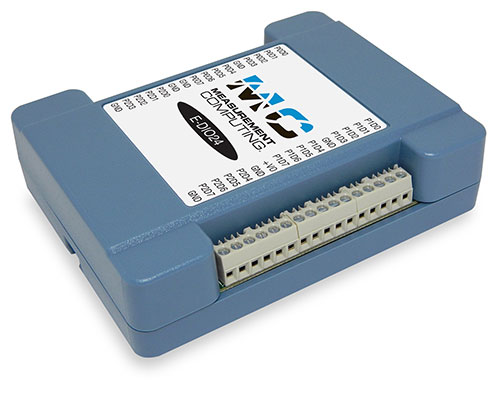
This module costs $320 and has the following features:
More information can be found in the E-DIO24 product description.
The following lines are needed in the EPICS startup script for the multifunction driver.
## Configure port driver
# MultiFunctionConfig(portName,        # The name to give to this asyn port driver
#                     boardNum,        # The number of this board assigned by the Measurement Computing Instacal program
#                     maxInputPoints,  # Maximum number of input points for waveform digitizer
#                     maxOutputPoints) # Maximum number of output points for waveform generator
MultiFunctionConfig("1608G_1", 1, 1048576, 1048576)
dbLoadTemplate("1608G.substitutions.big")
The measComp module comes with example iocBoot/ directories that contain example startup scripts and example substitutions files. These directories are iocUSB1208, iocUSB1608G, iocUSB1608G-2A0, iocUSB2408, iocUSB231, iocUSBC9513, iocUSBCTR, and iocMeasCompDemo.
The following tables list the database template files that are used with the multi-function modules.
| EPICS record name | EPICS record type | asyn interface | drvInfo string | Description |
|---|---|---|---|---|
| measCompAnalogIn.template. This database is loaded once for each analog input channel. | ||||
| $(P)$(R) | ai | asynInt32 | ANALOG_IN_VALUE | Analog input value. This is converted from the 16-bit unsigned integer device units from the driver to engineering units using the EGUL and EGUF fields. This field should be periodically scanned, since it is not currently polled in the driver, so I/O Intr scanning cannot be used. |
| $(P)$(R)Range | mbbo | asynInt32 | ANALOG_IN_RANGE | Input range for this analog input channel. Choices are determined at run time based on the model in use. |
| $(P)$(R)Type | mbbo | asynInt32 | ANALOG_IN_TYPE | Input type (e.g. "Volts", "TC deg", etc.) for this analog input channel. Choices are determined at run time based on the model in use. |
| measCompAnalogOut.template. This database is loaded once for each analog input channel. | ||||
| $(P)$(R) | ai | asynInt32 | ANALOG_OUT_VALUE | Analog output value. This is converted from engineering units to the 16-bit unsigned integer device units for the driver using the EGUL and EGUF fields. |
| $(P)$(R)Range | mbbo | asynInt32 | ANALOG_OUT_RANGE | Output range for this analog output channel. Choices are determined at run time based on the model in use. |
| $(P)$(R)Return | ai | asynInt32 | ANALOG_OUT_VALUE | Analog output value to return to at the end of a pulse. This is converted from engineering units to the 16-bit unsigned integer device units for the driver using the EGUL and EGUF fields. |
| $(P)$(R)Pulse | bo | N.A. | N.A. | Choices are "Normal" and "Pulse". In Normal mode the Return record is ignored. In Pulse mode the $(P)($R) output is written to to hardware, followed immediately by writing the $(P)$(R)Return value. |
| $(P)$(R)TweakVal | ao | N.A. | N.A. | The amount by which to tweak the out when the Tweak record is processed. |
| $(P)$(R)TweakUp | calcout | N.A. | N.A. | Tweaks the output up by TweakVal. |
| $(P)$(R)TweakDown | calcout | N.A. | N.A. | Tweaks the output down by TweakVal. |
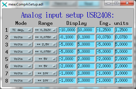
The following is the medm screen for controlling the analog input records for the USB-1608GX-2AO. Note that the engineering units limits (EGUL and EGUF) do not have to be in volts, they can be in any units such as "percent", "degrees", etc.
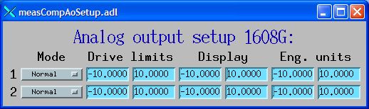
The following is the medm screen for controlling the analog output records for the USB-1608GX-2AO. Note that the engineering units limits (EGUL and EGUF) do not have to be in volts, they can be in any units such as "percent", "degrees", etc. The drive limits can be more restrictive than the full +-10V output range of the analog outputs.
| EPICS record name | EPICS record type | asyn interface | drvInfo string | Description |
|---|---|---|---|---|
| measCompTemperatureIn.template. This database is loaded once for each temperature input channel. | ||||
| $(P)$(R) | ai | asynFloat64 | TEMPERATURE_IN_VALUE | Temperature input value. This field should be periodically scanned, since it is not currently polled in the driver, so I/O Intr scanning cannot be used. |
| $(P)$(R)Scale | mbbo | asynInt32 | TEMPERATURE_SCALE | Temperature scale (units) for this temperature input channel. Choices are "Celsius" (0), "Fahrenheit" (1), "Kelvin" (2), "Volts" (4), and "Noscale" (5). |
| $(P)$(R)TCType | mbbo | asynInt32 | THERMOCOUPLE_TYPE | Thermocouple type. Choices are "Type J" (1), "Type K" (2), "Type T" (3), "Type 4" (4), "Type R" (5), "Type S" (6), "Type B" (7), "Type N" (8) |
| $(P)$(R)Filter | mbbo | asynInt32 | TEMPERATURE_FILTER | Temperature filter. Choices are "Filter" (0) and "No filter" (0x400) |
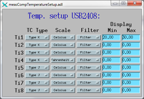
The following is the main medm screen for configuring the analog/temperature inputs on the USB-2408-2AO.
| EPICS record name | EPICS record type | asyn interface | drvInfo string | Description |
|---|---|---|---|---|
| measCompBinaryIn.template. This database is loaded once for each binary I/O bit. | ||||
| $(P)$(R) | bi | asynUInt32Digital | DIGITAL_INPUT | Digital input value. The MASK parameter in the INP link defines which bit is used. The binary inputs are polled by the driver poller thread, so these records should have SCAN="I/O Intr". |
| measCompLongIn.template. This database is loaded once for each binary I/O register. | ||||
| $(P)$(R) | longin | asynUInt32Digital | DIGITAL_INPUT | Digital input value as a word, rather than individual bits. The MASK parameter in the INP link defines which bits are used. The binary inputs are polled by the driver poller thread, so this record should have SCAN="I/O Intr". |
| measCompBinaryOut.template. This database is loaded once for each binary I/O bit. | ||||
| $(P)$(R) | bo | asynUInt32Digital | DIGITAL_OUTPUT | Digital output value. The MASK parameter in the INP link defines which bit is used. |
| $(P)$(R)_RBV | bi | asynUInt32Digital | DIGITAL_OUTPUT | Digital output value readback. The MASK parameter in the INP link defines which bit is used. |
| measCompLongOut.template. This database is loaded once for each binary I/O register. | ||||
| $(P)$(R) | longout | asynUInt32Digital | DIGITAL_OUTPUT | Digital output value as a word, rather than individual bits. The MASK parameter in the INP link defines which bits are used. |
| $(P)$(R)_RBV | longin | asynUInt32Digital | DIGITAL_OUTPUT | Digital output value readback as a word, rather than individual bits. The MASK parameter in the INP link defines which bits are used. |
| measCompBinaryDir.template. This database is loaded once for each binary I/O bit. | ||||
| $(P)$(R) | bo | asynUInt32Digital | DIGITAL_DIRECTION | Direction of this I/O line, "In" (0) or "Out" (1). The MASK parameter in the INP link defines which bit is used. |
| EPICS record name | EPICS record type | asyn interface | drvInfo string | Description |
|---|---|---|---|---|
| measCompPulseGen.template. This database is loaded once for each pulse generator. | ||||
| $(P)$(R)Run | bo | asynUInt32 | PULSE_RUN | "Run" (1) starts the pulse generator, "Stop" (0) stops the pulse generator. Note that ideally this record should go back to 0 when the pulse generator is done, if it is outputting a finite number of pulses (see Count record). But unfortunately the Measurement Computing library does not have a way to query the status of the timer to see if it is done, so this is not possible. |
| $(P)$(R)Period | ao | asynFloat64 | PULSE_PERIOD | Pulse period, in seconds. The time between pulses can be defined either with the Period or with the Frequency; whenever one record is changed the other is updated with the new calculated value. |
| $(P)$(R)Frequency | ao | N.A. | N.A. | Pulse frequency, in seconds. The Frequency calculates a new value of the Period, and sends the period value to the driver. |
| $(P)$(R)Width | ao | asynFloat64 | PULSE_WIDTH | Pulse width, in seconds. The allowed range is 15.625 ns to (Period-15.625 ns). |
| $(P)$(R)Delay | ao | asynFloat64 | PULSE_DELAY | Initial pulse delay in seconds after Run is set to 1. |
| $(P)$(R)Count | longout | asynInt32 | PULSE_COUNT | Number of pulses to output. If the Count is 0 then the pulse generator runs continuously until Run is set to 0. |
| $(P)$(R)IdleState | bo | asynInt32 | PULSE_IDLE_STATE | The idle state of the pulse output line, "Low" (0) or "High" (1). This determines the polarity of the pulse, i.e. positive going or negative going. |
| EPICS record name | EPICS record type | asyn interface | drvInfo string | Description |
|---|---|---|---|---|
| measCompWaveformDig.template. This database is loaded once per module. | ||||
| $(P)$(R)NumPoints | longout | asynInt32 | WAVEDIG_NUM_POINTS | Number of points to digitize. This cannot be more than the value of maxInputPoints that was specified in USB1608GConfig. |
| $(P)$(R)FirstChan | mbbo | asynInt32 | WAVEDIG_FIRST_CHAN | First channel to digitize. "1" (0) to "8" (7). The database currently assumes differential inputs, so only 8 inputs are available, though this can easily be extended to 16. |
| $(P)$(R)NumChans | mbbo | asynInt32 | WAVEDIG_NUM_CHANS | Number of channels to digitize. "1" (0) to "8" (7). The maximum valid number is 8-FirstChan+1. The database currently assumes differential inputs, so only 8 inputs are available, though this can easily be extended to 16. |
| $(P)$(R)TimeWF | waveform | asynFloat32Array | WAVEDIG_TIME_WF | Timebase waveform. These values are calculated when Dwell or NumPoints are changed. It is typically used as the X-axis in plots. |
| $(P)$(R)CurrentPoint | longin | asynInt32 | WAVEDIG_CURRENT_POINT | The current point being collected. This does not always increment by 1 because the device can transfer data in blocks. |
| $(P)$(R)Dwell | ao | asynFloat64 | WAVEDIG_DWELL | The time per point in seconds. The minimum time is 2 microseconds times NumChans. |
| $(P)$(R)TotalTime | ai | asynFloat64 | WAVEDIG_TOTAL_TIME | The total time to digitize NumChans*NumPoints. |
| $(P)$(R)ExtTrigger | bo | asynInt32 | WAVEDIG_EXT_TRIGGER | The trigger source, "Internal" (0) or "External" (1). |
| $(P)$(R)ExtClock | bo | asynInt32 | WAVEDIG_EXT_CLOCK | The clock source, "Internal" (0) or "External" (1). If External is used then the Dwell record does not control the digitization rate, it is controlled by the external clock. However Dwell should be set to approximately the correct value if possible, because that controls what type of data transfers the device uses. |
| $(P)$(R)Continuous | bo | asynInt32 | WAVEDIG_CONTINUOUS | Values are "One-shot" (0) or "Continuous" (1). This controls whether the device stops when acquisition is complete, or immediately begins another acquisition. Typically "One-shot" is used, because the driver is currently not double-buffered, so data could be overwritten before the driver has a chance to read the data. One exception is when using Retrigger=Enable and TriggerCount less than NumPoints. In that case each trigger will only collect TriggerCount samples, and one wants to use Continuous so that it collects the next TriggerCount samples on the next trigger input. |
| $(P)$(R)AutoRestart | bo | asynInt32 | WAVEDIG_AUTO_RESTART | Values are "Disable" (0) and "Enable" (1). This controls whether the driver automatically starts another acquire when the previous one completes. This is different from Continuous mode described above, because this is a software restart that only happens after the driver has read the buffer from the previous acquisition. |
| $(P)$(R)Retrigger | bo | asynInt32 | WAVEDIG_RETRIGGER | Values are "Disable" (0) and "Enable" (1). This controls whether the device rearms the trigger input after a trigger is received. |
| $(P)$(R)TriggerCount | longout | asynInt32 | WAVEDIG_TRIGGER_COUNT | This controls how many samples are collected on each trigger input. 0 means collect NumPoint samples. If TriggerCount is less than NumPoints, Retrigger=Enable and Continuous=Enable then each time a trigger is received TriggerCount samples will be collected. |
| $(P)$(R)BurstMode | bo | asynInt32 | WAVEDIG_BURST_MODE | Values are "Disable" (0) and "Enable" (1). This controls whether the device digitizes all NumChans channels as quickly as possible during each sample, or whether it digitizes successive channels at evenly spaced time intevals during the Dwell time. Enabling BurstMode means that all channels are digitized 2 microseconds apart. This can reduce the accuracy if the channels have very different voltages because of the settling time and slew rate limitations of the system. |
| $(P)$(R)Run | busy | asynInt32 | WAVEDIG_RUN | Values are "Stop" (0) and "Run" (1). This starts and stops the waveform digitizer. |
| $(P)$(R)ReadWF | busy | asynInt32 | WAVEDIG_READ_WF | Values are "Done" (0) and "Read" (1). This reads the waveform data from the device buffers into the waveform records. Note that the driver always reads device when acquisition stops, so for quick acquisitions this record can be Passive. To see partial data during long acquisitions this record can be periodically processed. |
| measCompWaveformDigN.template. This database is loaded for each digitizer input channel. | ||||
| $(P)$(R)VoltWF | waveform | asynFloat64Array | WAVEDIG_VOLT_WF | This waveform record contains the digitizer waveform data for channel N. This record has scan=I/O Intr, and it will process whenever acquisition completes, or whenever the ReadWF record above processes. The data are in volts. |

| EPICS record name | EPICS record type | asyn interface | drvInfo string | Description |
|---|---|---|---|---|
| measCompWaveformGen.template. This database is loaded once per module. | ||||
| $(P)$(R)NumPoints | longin | asynInt32 | WAVEGEN_NUM_POINTS | Number of points output waveform. The value of this record is equal to UserNumPoints if user-defined waveforms are selected, or IntNumPoints if internal predefined waveforms are selected. |
| $(P)$(R)UserNumPoints | longout | asynInt32 | WAVEGEN_USER_NUM_POINTS | Number of points in user-defined output waveforms. This cannot be more than the value of maxOutputPoints that was specified in USB1608GConfig. |
| $(P)$(R)IntNumPoints | longout | asynInt32 | WAVEGEN_INT_NUM_POINTS | Number of points in internal predefined output waveforms. This cannot be more than the value of maxOutputPoints that was specified in USB1608GConfig. |
| $(P)$(R)UserTimeWF | waveform | asynFloat32Array | WAVEDIG_USER_TIME_WF | Timebase waveform for user-defined waveforms. These values are calculated when UserDwell or UserNumPoints are changed. It is typically used as the X-axis in plots. |
| $(P)$(R)IntTimeWF | waveform | asynFloat32Array | WAVEGEN_INT_TIME_WF | Timebase waveform for internal predefined waveforms. These values are calculated when IntDwell or IntNumPoints are changed. It is typically used as the X-axis in plots. |
| $(P)$(R)CurrentPoint | longin | asynInt32 | WAVEGEN_CURRENT_POINT | The current point being output. This does not always increment by 1 because the device can transfer data in blocks. |
| $(P)$(R)Frequency | ai | asynFloat64 | WAVEGEN_FREQUENCY | The output frequency (waveforms/second). The value of this record is equal to UserFrequency if user-defined waveforms are selected, or IntFrequency if internal predefined waveforms are selected. |
| $(P)$(R)Dwell | ai | asynFloat64 | WAVEGEN_DWELL | The output dwell time or period (seconds/sample). The value of this record is equal to UserDwell if user-defined waveforms are selected, or IntDwell if internal predefined waveforms are selected. |
| $(P)$(R)UserDwell | ao | asynFloat64 | WAVEGEN_USER_DWELL | The output dwell time or period (seconds/sample) for user-defined waveforms. This record is automatically changed if UserFrequency is modified. |
| $(P)$(R)IntDwell | ao | asynFloat64 | WAVEGEN_INT_DWELL | The output dwell time or period (seconds/sample) for internal predefined waveforms. This record is automatically changed if IntFrequency is modified. |
| $(P)$(R)UserFrequency | ao | N.A. | N.A. | The output frequency (waveforms/second) for user-defined waveforms. This record computes UserDwell and writes to that record. This record is automatically changed if UserDwell is modified. |
| $(P)$(R)IntFrequency | ao | N.A. | N.A. | The output frequency (waveforms/second) for internal predefined waveforms. This record computes IntDwell and writes to that record. This record is automatically changed if IntDwell is modified. |
| $(P)$(R)TotalTime | ai | asynFloat64 | WAVEGEN_TOTAL_TIME | The total time to output the waveforms. This is Dwell*NumPoints. |
| $(P)$(R)ExtTrigger | bo | asynInt32 | WAVEGEN_EXT_TRIGGER | The trigger source, "Internal" (0) or "External" (1). |
| $(P)$(R)ExtClock | bo | asynInt32 | WAVEGEN_EXT_CLOCK | The clock source, "Internal" (0) or "External" (1). If External is used then the Dwell record does not control the output rate, it is controlled by the external clock. However Dwell should be set to approximately the correct value if possible, because that controls what type of data transfers the device uses. |
| $(P)$(R)Continuous | bo | asynInt32 | WAVEGEN_CONTINUOUS | Values are "One-shot" (0) or "Continuous" (1). This controls whether the device stops when the output waveform is complete, or immediately begins again at the start of the waveform. |
| $(P)$(R)Retrigger | bo | asynInt32 | WAVEGEN_RETRIGGER | Values are "Disable" (0) and "Enable" (1). This controls whether the device rearms the trigger input after a trigger is received. |
| $(P)$(R)TriggerCount | longout | asynInt32 | WAVEGEN_TRIGGER_COUNT | This controls how many values are output on each trigger input. 0 means output NumPoints samples. If TriggerCount is less than NumPoints, Retrigger=Enable and Continuous=Enable then each time a trigger is received TriggerCount samples will be output. |
| $(P)$(R)Run | busy | asynInt32 | WAVEGEN_RUN | Values are "Stop" (0) and "Run" (1). This starts and stops the waveform generator. |
| measCompWaveformGenN.template. This database is loaded for each waveform generator output channel. | ||||
| $(P)$(R)UserWF | waveform | asynFloat32Array | WAVEGEN_USER_WF | This waveform record contains the user-defined waveform generator data for channel N. The data are in volts. These data are typically generated by an EPICS Channel Access client. |
| $(P)$(R)InternalWF | waveform | asynFloat32Array | WAVEGEN_INT_WF | This waveform record contains the internal predefined waveform generator data for channel N. The data are in volts. |
| $(P)$(R)Enable | bo | asynInt32 | WAVEGEN_ENABLE | Values are "Disable" and "Enable". Controls whether channel N output is enabled. |
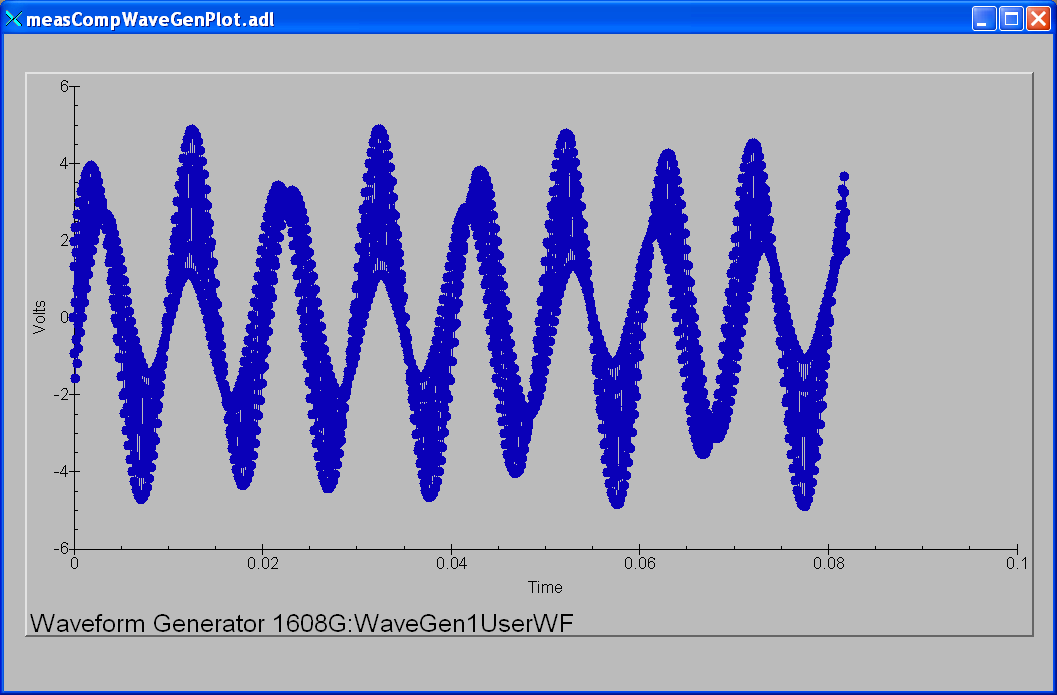
| $(P)$(R)Type | mbbo | asynInt32 | WAVEGEN_WAVE_TYPE | Controls the waveform type on channel N. Values are "User-defined" and "Sin wave", "Square wave", "Sawtooth", "Pulse", or "Random". Note that if any channel is "User-defined" then all channels must be. Note that all internally predefined waveforms are symmetric about 0 volts. To output unipolar signals the Offset should be set to +-Amplitude/2. |
| $(P)$(R)PulseWidth | ao | asynFloat64 | WAVEGEN_PULSE_WIDTH | Controls the pulse width in seconds if Type is "Pulse". |
| $(P)$(R)Amplitude | ao | asynFloat64 | WAVEGEN_AMPLITUDE | Controls the amplitude of the waveform. For internally predefined waveforms this directly controls the peak-to-peak amplitude in volts. For user-defined waveforms this is a scale factor that multiplies the values in the waveform, i.e. 1.0 outputs the user-defined waveform unchanged, 2.0 increases the amplitide by 2, etc. For both internal and used-defined waveforms changing the sign of the Amplitude controls the polarity of the signal. |
| $(P)$(R)Offset | ao | asynFloat64 | WAVEGEN_OFFSET | Controls the offset of the waveform in volts. For user-defined waveforms, this value is added to the waveform, i.e. 0.0 outputs the user-defined waveform unchanged, 1.0 adds 1 volt, etc. |
| EPICS record name | EPICS record type | asyn interface | drvInfo string | Description |
|---|---|---|---|---|
| measCompTrigger.template. This database is loaded once per module. | ||||
| $(P)$(R)Mode | mbbo | asynInt32 | TRIGGER_MODE | The mode of the external trigger input. Choices are "Positive edge", "Negative edge", "High", and "Low". |
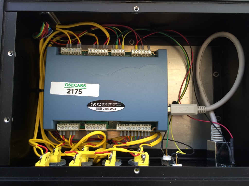
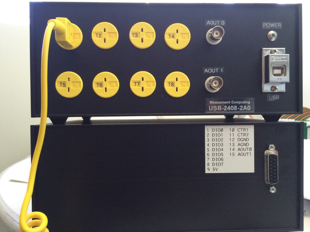
The following photo shows a box we built to house the USB-2408-2AO and provide I/O connections. .
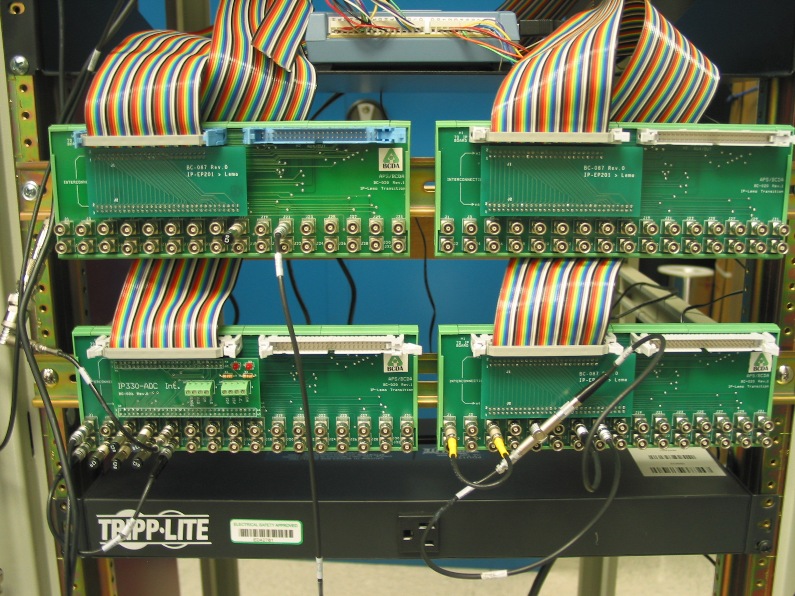
The following photo shows the BCDA BC-020 LEMO breakout panels wired to the USB-1608GX-2AO. These are the lower 2 BC-020 panels in this photo. A BC-020 with a BC-026 daughter card is used for the analog signals (lower left), and a BC-020 with a BC-087 daughter card for the digital signals (lower right).
      Digital I/O using BC-087 daughter card

50-pin ribbon      USB-1608GX      BC-020   EPICS Function
connector pin    screw terminal   connector
 1                DIO0               J1     Digital I/O bit 0
 2                DIO1               J2     Digital I/O bit 1
 3                DIO2               J3     Digital I/O bit 2
 4                DIO3               J4     Digital I/O bit 3
 5                DIO4               J5     Digital I/O bit 4
 6                DIO5               J6     Digital I/O bit 5
 7                DIO6               J7     Digital I/O bit 6
 8                DIO7               J8     Digital I/O bit 7
 9                 TMR               J9     Pulse generator output
10                 GND              J10     Grounded to avoid cross-talk
11                CTR0              J11     Counter 1 input
12                 GND              J12     Grounded to avoid cross-talk
13                CTR1              J13     Counter 2 input
14                 GND              J14     Grounded to avoid cross-talk
15                TRIG              J15     Trigger input for waveform generator and waveform digitizer
16                 GND              J16     Grounded to avoid cross-talk
17               A0CK0              J17     Waveform generator clock out
18                 GND              J18     Grounded to avoid cross-talk
19               A0CKI              J19     Waveform generator clock in
20                 GND              J20     Grounded to avoid cross-talk
21               AICK0              J21     Waveform digitizer clock out
22                 GND              J16     Grounded to avoid cross-talk
23               AICKI              J17     Waveform digitzer clock in
50                 GND           J1-J32     LEMO connectors outer shells


         Analog I/O using BC-026 daughter card

50-pin ribbon      USB-1608GX      BC-020   EPICS Function
connector pin    screw terminal   connector
 1                CH0H               J1     Analog input 1 +
 2                CH0L               J1     Analog input 1 -
 3                AGND              N.C     Analog ground
 4                CH1H               J2     Analog input 2 +
 5                CH1L               J2     Analog input 2 -
 6                AGND              N.C     Analog ground
 7                CH2H               J3     Analog input 3 +
 8                CH2L               J3     Analog input 3 -
 9                AGND              N.C     Analog ground
10                CH3H               J4     Analog input 4 +
11                CH3L               J4     Analog input 4 -
12                AGND              N.C     Analog ground
13                CH4H               J5     Analog input 5 +
14                CH4L               J5     Analog input 5 -
15                AGND              N.C     Analog ground
16                CH5H               J6     Analog input 6 +
17                CH5L               J6     Analog input 6 -
18                AGND              N.C     Analog ground
19                CH6H               J7     Analog input 7 +
20                CH6L               J7     Analog input 7 -
21                AGND              N.C     Analog ground
22                CH7H               J8     Analog input 8 +
23                CH7L               J8     Analog input 8 -
24                AGND              N.C     Analog ground
25               AOUT0               J9     Analog output 1
26                AGND               J9     Analog ground
27                AGND              N.C     Analog ground
28               AOUT1              J10     Analog output 1
29                AGND              J10     Analog ground

Note: the "Analog input N +" lines are connected to the Lemo center pin,
and the "Analog input N -" lines are connected to the Lemo shell.
The following summarizes a simple test of the precision and accuracy of the analog outputs and analog inputs of the USB-1608GX-2AO. The test configuration was with Analog Output 0 connected to Analog Input 0, and also to a Keithley 2700 digital multimeter. The Keithley is a 6.5 digit (22 bit) device, so it can be used to measure the accuracy of the USB-1608GX-2AO analog output, and provide the "true" value to measure the accuracy of the analog input. The 1608GX analog inputs records and the Keithley input had SCAN=0.1 second, so new readings were being made at 10Hz. The following IDL test program was used to drive the analog output from -10V to +10V in 0.1V steps. 10 readings were made of the 1608GX analog inputs, and one reading of the Keithley at each voltage step. These tests were done with the +-10V range of the analog outputs and analog inputs. Since these are 16-bit devices, one bit is 20V/65536 = 0.000305 volts.
pro test_analog_performance_1608,  ao=ao, ai=ai, min_volts=min_volts, max_volts=max_volts, $
                                   step_volts=step_volts, num_samples=num_samples, delay=delay, $
                                   keithley=keithley, results

  if (n_elements(ao)          eq 0) then ao          = '1608G:Ao1'
  if (n_elements(ai)          eq 0) then ai          = '1608G:Ai1'
  if (n_elements(min_volts)   eq 0) then min_volts   = -10.0
  if (n_elements(max_volts)   eq 0) then max_volts   =  10.0
  if (n_elements(step_volts)  eq 0) then step_volts  = 0.1
  if (n_elements(num_samples) eq 0) then num_samples = 10
  if (n_elements(delay)       eq 0) then delay       = 0.1
  if (n_elements(keithley)    eq 0) then keithley    = '13LAB:DMM2Dmm_raw.VAL'

  output = min_volts
  samples = dblarr(num_samples)
  num_points = ((max_volts - min_volts) / step_volts + 0.5) + 1
  results = dblarr(4, num_points)
  for i=0, num_points-1 do begin
    output = min_volts + i*step_volts
    t = caput(ao, output)
    wait, 2*delay
    for j=0, num_samples-1 do begin
      wait, delay
      t = caget(ai, temp)
      samples[j] = temp
    endfor
    m = moment(samples)
    results[0,i] = output
    results[1,i] = m[0]
    results[2,i] = sqrt(m[1])
    t = caget(keithley, temp)
    results[3,i] = temp
    print, results[0,i], results[1,i], results[2,i], results[3,i]
  endfor
end
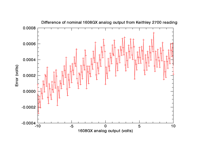
The following plot shows the difference of the nominal 1608GX analog output voltage from the Keithley 2700 reading. The mean error is 0.000312V, or just over 1 bit. The RMS error is 0.000203V, or less than 1 bit.
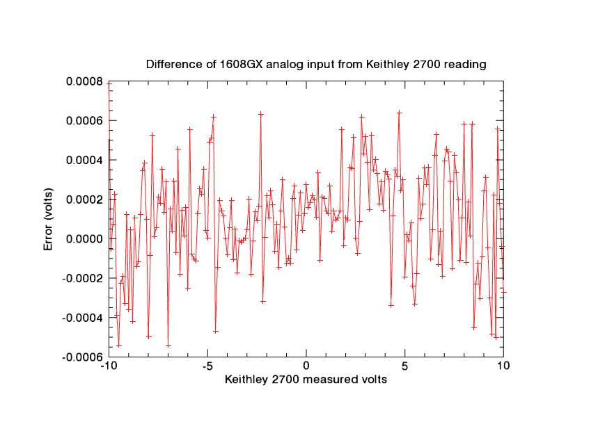
The following plot shows the difference of the mean of 10 readings of the 1608GX analog input voltage from the Keithley 2700 reading. The mean error is 0.000106V, less than 1 bit. The RMS error is 0.000259V, also less than 1 bit.
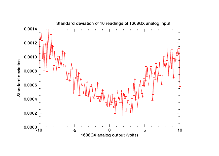
The following plot shows the standard deviation of 10 readings of the 1608GX analog input voltage. The values range from about 0.001V (~3 bits) at +-10V to less than 0.0003V (1 bit) between -2 and +2V.
The following table contains all of the results from the tests.
| 1608GX analog output (nominal) | 1608GX analog input (mean of 10 readings) | Std. Dev. of 10 1608GX analog input readings | Keithley 2700 reading |
|---|---|---|---|
| -10.00000 | -9.99930 | 0.00084 | -10.00008 |
| -9.90000 | -9.89978 | 0.00130 | -9.89972 |
| -9.80000 | -9.79986 | 0.00126 | -9.79994 |
| -9.70000 | -9.69964 | 0.00134 | -9.69987 |
| -9.60000 | -9.60018 | 0.00123 | -9.59979 |
| -9.50000 | -9.50057 | 0.00099 | -9.50003 |
| -9.40000 | -9.40020 | 0.00117 | -9.39997 |
| -9.30000 | -9.30010 | 0.00080 | -9.29991 |
| -9.20000 | -9.20046 | 0.00105 | -9.20013 |
| -9.10000 | -9.09996 | 0.00118 | -9.10009 |
| -9.00000 | -9.00035 | 0.00122 | -8.99999 |
| -8.90000 | -8.90016 | 0.00079 | -8.90021 |
| -8.80000 | -8.80061 | 0.00118 | -8.80019 |
| -8.70000 | -8.69996 | 0.00138 | -8.70007 |
| -8.60000 | -8.60044 | 0.00112 | -8.60030 |
| -8.50000 | -8.50004 | 0.00098 | -8.49992 |
| -8.40000 | -8.39973 | 0.00103 | -8.39985 |
| -8.30000 | -8.29975 | 0.00132 | -8.30009 |
| -8.20000 | -8.19965 | 0.00108 | -8.20003 |
| -8.10000 | -8.09986 | 0.00115 | -8.09995 |
| -8.00000 | -8.00040 | 0.00079 | -7.99990 |
| -7.90000 | -7.90021 | 0.00088 | -7.90012 |
| -7.80000 | -7.79950 | 0.00107 | -7.80002 |
| -7.70000 | -7.69998 | 0.00099 | -7.69999 |
| -7.60000 | -7.60018 | 0.00092 | -7.60024 |
| -7.50000 | -7.49990 | 0.00080 | -7.50011 |
| -7.40000 | -7.39986 | 0.00097 | -7.40004 |
| -7.30000 | -7.29992 | 0.00101 | -7.30027 |
| -7.20000 | -7.20006 | 0.00085 | -7.20019 |
| -7.10000 | -7.09953 | 0.00100 | -7.09982 |
| -7.00000 | -7.00060 | 0.00088 | -7.00006 |
| -6.90000 | -6.89986 | 0.00097 | -6.90001 |
| -6.80000 | -6.79988 | 0.00089 | -6.79992 |
| -6.70000 | -6.69984 | 0.00107 | -6.70013 |
| -6.60000 | -6.60017 | 0.00091 | -6.60010 |
| -6.50000 | -6.49958 | 0.00088 | -6.50003 |
| -6.40000 | -6.40043 | 0.00105 | -6.40025 |
| -6.30000 | -6.30005 | 0.00088 | -6.30020 |
| -6.20000 | -6.20008 | 0.00085 | -6.20009 |
| -6.10000 | -6.10016 | 0.00076 | -6.10032 |
| -6.00000 | -6.00052 | 0.00068 | -6.00026 |
| -5.90000 | -5.89963 | 0.00077 | -5.90018 |
| -5.80000 | -5.80050 | 0.00076 | -5.80043 |
| -5.70000 | -5.70013 | 0.00066 | -5.70003 |
| -5.60000 | -5.60006 | 0.00066 | -5.59995 |
| -5.50000 | -5.50008 | 0.00082 | -5.50021 |
| -5.40000 | -5.39989 | 0.00090 | -5.40015 |
| -5.30000 | -5.29982 | 0.00081 | -5.30005 |
| -5.20000 | -5.19997 | 0.00087 | -5.20032 |
| -5.10000 | -5.10021 | 0.00048 | -5.10025 |
| -5.00000 | -5.00011 | 0.00054 | -5.00011 |
| -4.90000 | -4.89986 | 0.00071 | -4.90035 |
| -4.80000 | -4.79976 | 0.00070 | -4.80027 |
| -4.70000 | -4.69960 | 0.00082 | -4.70021 |
| -4.60000 | -4.60090 | 0.00054 | -4.60043 |
| -4.50000 | -4.50050 | 0.00072 | -4.50035 |
| -4.40000 | -4.40012 | 0.00076 | -4.40032 |
| -4.30000 | -4.30039 | 0.00045 | -4.30053 |
| -4.20000 | -4.20005 | 0.00066 | -4.20016 |
| -4.10000 | -4.10010 | 0.00068 | -4.10010 |
| -4.00000 | -4.00012 | 0.00062 | -4.00004 |
| -3.90000 | -3.90018 | 0.00060 | -3.90023 |
| -3.80000 | -3.80002 | 0.00059 | -3.80021 |
| -3.70000 | -3.70019 | 0.00049 | -3.70009 |
| -3.60000 | -3.60027 | 0.00056 | -3.60032 |
| -3.50000 | -3.50042 | 0.00063 | -3.50025 |
| -3.40000 | -3.40017 | 0.00048 | -3.40016 |
| -3.30000 | -3.30043 | 0.00045 | -3.30042 |
| -3.20000 | -3.20034 | 0.00064 | -3.20033 |
| -3.10000 | -3.10027 | 0.00066 | -3.10027 |
| -3.00000 | -3.00047 | 0.00043 | -3.00052 |
| -2.90000 | -2.90025 | 0.00060 | -2.90045 |
| -2.80000 | -2.80021 | 0.00044 | -2.80003 |
| -2.70000 | -2.70033 | 0.00038 | -2.70032 |
| -2.60000 | -2.60011 | 0.00058 | -2.60024 |
| -2.50000 | -2.50001 | 0.00063 | -2.50010 |
| -2.40000 | -2.40015 | 0.00051 | -2.40032 |
| -2.30000 | -2.29960 | 0.00043 | -2.30023 |
| -2.20000 | -2.20050 | 0.00041 | -2.20019 |
| -2.10000 | -2.10040 | 0.00048 | -2.10041 |
| -2.00000 | -2.00012 | 0.00054 | -2.00034 |
| -1.90000 | -1.90018 | 0.00044 | -1.90028 |
| -1.80000 | -1.80026 | 0.00044 | -1.80050 |
| -1.70000 | -1.70025 | 0.00062 | -1.70042 |
| -1.60000 | -1.60043 | 0.00041 | -1.60036 |
| -1.50000 | -1.50054 | 0.00044 | -1.50061 |
| -1.40000 | -1.40035 | 0.00037 | -1.40021 |
| -1.30000 | -1.30001 | 0.00043 | -1.30015 |
| -1.20000 | -1.20006 | 0.00035 | -1.20036 |
| -1.10000 | -1.10024 | 0.00048 | -1.10029 |
| -1.00000 | -1.00035 | 0.00052 | -1.00022 |
| -0.90000 | -0.90056 | 0.00036 | -0.90046 |
| -0.80000 | -0.80052 | 0.00050 | -0.80040 |
| -0.70000 | -0.70011 | 0.00041 | -0.70032 |
| -0.60000 | -0.60029 | 0.00036 | -0.60056 |
| -0.50000 | -0.50056 | 0.00035 | -0.50050 |
| -0.40000 | -0.40031 | 0.00032 | -0.40042 |
| -0.30000 | -0.30042 | 0.00030 | -0.30065 |
| -0.20000 | -0.20053 | 0.00048 | -0.20058 |
| -0.10000 | -0.10037 | 0.00041 | -0.10050 |
| 0.00000 | 0.00018 | 0.00030 | -0.00009 |
| 0.10000 | 0.09986 | 0.00046 | 0.09970 |
| 0.20000 | 0.19995 | 0.00032 | 0.19977 |
| 0.30000 | 0.30005 | 0.00035 | 0.29983 |
| 0.40000 | 0.39979 | 0.00046 | 0.39959 |
| 0.50000 | 0.49979 | 0.00032 | 0.49968 |
| 0.60000 | 0.60008 | 0.00028 | 0.59974 |
| 0.70000 | 0.69941 | 0.00041 | 0.69952 |
| 0.80000 | 0.79979 | 0.00019 | 0.79957 |
| 0.90000 | 0.89986 | 0.00037 | 0.89965 |
| 1.00000 | 0.99956 | 0.00032 | 0.99942 |
| 1.10000 | 1.09966 | 0.00051 | 1.09953 |
| 1.20000 | 1.19982 | 0.00045 | 1.19955 |
| 1.30000 | 1.29940 | 0.00041 | 1.29936 |
| 1.40000 | 1.39959 | 0.00041 | 1.39945 |
| 1.50000 | 1.49990 | 0.00035 | 1.49981 |
| 1.60000 | 1.59969 | 0.00035 | 1.59959 |
| 1.70000 | 1.69979 | 0.00052 | 1.69965 |
| 1.80000 | 1.80029 | 0.00016 | 1.79974 |
| 1.90000 | 1.89944 | 0.00050 | 1.89948 |
| 2.00000 | 1.99966 | 0.00047 | 1.99956 |
| 2.10000 | 2.09973 | 0.00045 | 2.09964 |
| 2.20000 | 2.19980 | 0.00041 | 2.19944 |
| 2.30000 | 2.29984 | 0.00044 | 2.29948 |
| 2.40000 | 2.40006 | 0.00023 | 2.39955 |
| 2.50000 | 2.49934 | 0.00032 | 2.49933 |
| 2.60000 | 2.59937 | 0.00038 | 2.59945 |
| 2.70000 | 2.69963 | 0.00054 | 2.69954 |
| 2.80000 | 2.79994 | 0.00032 | 2.79932 |
| 2.90000 | 2.90010 | 0.00033 | 2.89967 |
| 3.00000 | 3.00026 | 0.00021 | 2.99974 |
| 3.10000 | 3.09990 | 0.00027 | 3.09951 |
| 3.20000 | 3.19976 | 0.00041 | 3.19961 |
| 3.30000 | 3.30022 | 0.00022 | 3.29970 |
| 3.40000 | 3.39977 | 0.00061 | 3.39942 |
| 3.50000 | 3.49990 | 0.00045 | 3.49950 |
| 3.60000 | 3.59991 | 0.00068 | 3.59958 |
| 3.70000 | 3.69952 | 0.00039 | 3.69934 |
| 3.80000 | 3.79974 | 0.00052 | 3.79945 |
| 3.90000 | 3.89969 | 0.00043 | 3.89954 |
| 4.00000 | 3.99994 | 0.00029 | 3.99960 |
| 4.10000 | 4.09967 | 0.00042 | 4.09935 |
| 4.20000 | 4.19974 | 0.00063 | 4.19944 |
| 4.30000 | 4.29950 | 0.00058 | 4.29984 |
| 4.40000 | 4.39973 | 0.00066 | 4.39961 |
| 4.50000 | 4.50001 | 0.00055 | 4.49966 |
| 4.60000 | 4.60005 | 0.00048 | 4.59973 |
| 4.70000 | 4.70014 | 0.00043 | 4.69951 |
| 4.80000 | 4.79982 | 0.00059 | 4.79957 |
| 4.90000 | 4.89995 | 0.00069 | 4.89965 |
| 5.00000 | 4.99925 | 0.00059 | 4.99945 |
| 5.10000 | 5.09960 | 0.00066 | 5.09958 |
| 5.20000 | 5.19963 | 0.00087 | 5.19964 |
| 5.30000 | 5.29952 | 0.00072 | 5.29944 |
| 5.40000 | 5.39925 | 0.00084 | 5.39949 |
| 5.50000 | 5.49926 | 0.00059 | 5.49959 |
| 5.60000 | 5.59918 | 0.00065 | 5.59935 |
| 5.70000 | 5.70004 | 0.00073 | 5.69973 |
| 5.80000 | 5.79989 | 0.00081 | 5.79979 |
| 5.90000 | 5.89972 | 0.00087 | 5.89954 |
| 6.00000 | 6.00000 | 0.00076 | 5.99964 |
| 6.10000 | 6.10001 | 0.00038 | 6.09973 |
| 6.20000 | 6.19986 | 0.00047 | 6.19950 |
| 6.30000 | 6.29947 | 0.00071 | 6.29958 |
| 6.40000 | 6.39973 | 0.00077 | 6.39968 |
| 6.50000 | 6.49986 | 0.00068 | 6.49943 |
| 6.60000 | 6.60005 | 0.00091 | 6.59952 |
| 6.70000 | 6.69947 | 0.00085 | 6.69960 |
| 6.80000 | 6.79939 | 0.00065 | 6.79935 |
| 6.90000 | 6.89924 | 0.00083 | 6.89944 |
| 7.00000 | 6.99989 | 0.00074 | 6.99950 |
| 7.10000 | 7.09972 | 0.00091 | 7.09926 |
| 7.20000 | 7.20012 | 0.00074 | 7.19968 |
| 7.30000 | 7.30004 | 0.00073 | 7.29975 |
| 7.40000 | 7.39934 | 0.00061 | 7.39950 |
| 7.50000 | 7.50002 | 0.00073 | 7.49960 |
| 7.60000 | 7.60003 | 0.00074 | 7.59969 |
| 7.70000 | 7.69967 | 0.00101 | 7.69948 |
| 7.80000 | 7.79947 | 0.00089 | 7.79958 |
| 7.90000 | 7.89972 | 0.00094 | 7.89961 |
| 8.00000 | 8.00027 | 0.00083 | 7.99969 |
| 8.10000 | 8.09934 | 0.00090 | 8.09945 |
| 8.20000 | 8.19971 | 0.00095 | 8.19952 |
| 8.30000 | 8.29963 | 0.00112 | 8.29961 |
| 8.40000 | 8.39997 | 0.00073 | 8.39939 |
| 8.50000 | 8.49903 | 0.00089 | 8.49948 |
| 8.60000 | 8.59962 | 0.00080 | 8.59985 |
| 8.70000 | 8.69950 | 0.00109 | 8.69963 |
| 8.80000 | 8.79945 | 0.00084 | 8.79975 |
| 8.90000 | 8.89973 | 0.00111 | 8.89982 |
| 9.00000 | 8.99980 | 0.00083 | 8.99956 |
| 9.10000 | 9.09993 | 0.00071 | 9.09962 |
| 9.20000 | 9.19966 | 0.00098 | 9.19971 |
| 9.30000 | 9.29918 | 0.00090 | 9.29948 |
| 9.40000 | 9.39910 | 0.00097 | 9.39958 |
| 9.50000 | 9.49987 | 0.00106 | 9.49965 |
| 9.60000 | 9.59890 | 0.00102 | 9.59940 |
| 9.70000 | 9.70004 | 0.00110 | 9.69948 |
| 9.80000 | 9.79974 | 0.00105 | 9.79956 |
| 9.90000 | 9.89935 | 0.00112 | 9.89939 |
| 10.00000 | 9.99951 | 0.00058 | 9.99978 |