areaDetector ADSC driver
August 9, 2011
Lewis Muir
University of Chicago
Table of Contents
- Introduction
- Dependencies
- Building
- Configuring
- Image Modes
- Trigger Modes
- Dark Images
- Driver Specific Values and Settings
- Screenshots
- Unsupported areaDetector
base
Features
- Limitations
Introduction
This is an EPICS
areaDetector
driver for ADSC detectors. Supported
models are: Q4 (with the upgrade to four computers), Q4r, Q210, Q210r, Q270, Q315,
and Q315r. This driver has been tested with the Q210 and Q210r. If you use this
driver, please report your success, noting your detector model, to the author.
Dependencies
This driver controls the detector via the detcon_lib_th detector control
library provided by ADSC. The detcon_lib_th library must date from 2008-06-30
or newer.
Building
By default, this driver is built against a simulated control library. To build against
the ADSC detcon_lib_th control library to control a real detector, follow
these steps:
- Build the ADSC auxlib library provided by ADSC
- Build the ADSC detcon_lib_th library provided by ADSC
- Copy and rename, or create a symlink to, the ADSC auxlib.a library so
that it has the name libauxlib.a to satisfy the EPICS build facility's
requirement that a library file name start with
lib
- Set USE_SIMADSC to NO in ADApp/adscSrc/Makefile
- Set ADSC_HOME in ADApp/adscSrc/Makefile
- Rebuild the areaDetector module
Configuring
This driver is configured via the adscConfig() function. If this is to
be used in an IOC, it must be called before iocInit(). It has the following
signature:
- int adscConfig(const char *portName, const char *modelName)
-
- portName
-
ASYN port name for the driver instance
- modelName
-
ADSC detector model name; must be one of Q4, Q4r, Q210,
Q210r, Q270, Q315, Q315r
The underlying ADSC control library obtains its configuration from the environment.
Therefore, the environment must be correctly configured (i.e. ADSC environment variables
set) for the ADSC control library before calling adscConfig().
If being used in an IOC, and an EPICS PV interface with the driver is desired, the
ADBase.template, NDFile.template, and adsc.template databases
should also be loaded for the driver instance.
There is an example IOC boot directory and startup script (iocBoot/iocAdsc/st.cmd)
provided with areaDetector.
Image Modes
Single
The Single mode acquires just one image.
Multiple
The Multiple mode acquires the number of images specified in $(P)$(R)NumImages_RBV.
Continuous
The Continuous mode acquires images indefinitely until last image
is set. In this mode, the last image of the acquisition must be signaled before
exposing the last image by setting $(P)$(R)ADSCLastImage to 1.
This requirement is due to how the underlying ADSC control library works.
Trigger Modes
Internal
The Internal mode will make the driver expose images on its own once the
acquisition is started.
Ext. Software
The Ext. Software mode will make the driver expose images only when told
to once the acquisition is started. A special protocol must be followed to trigger
each image exposure. This would normally be very simple, but because the ADSC control
library can report that an exposure did not work and should be retried after any
exposure, a more complex protocol is required.
The protocol is described in terms of the EPICS PV driver interface, but the same
rules apply if controlling the driver directly through ASYN. The protocol is as
follows:
- Wait for $(P)$(R)ExSwTrOkToExp to be Yes
- Set $(P)$(R)ExSwTrCtl to Start to start the exposure
- Set $(P)$(R)ExSwTrCtl to Stop to stop the exposure
- Wait for $(P)$(R)ExSwTrCtlRsp to be OK or Again
- If $(P)$(R)ExSwTrCtlRsp is Again, the exposure did not work
and should be tried again
Note that care must be taken when waiting for $(P)$(R)ExSwTrCtlRsp to be
OK or Again to ensure the PV value is not stale (i.e. from the
previous exposure). There are at least two methods to ensure this:
- Use a CA monitor on $(P)$(R)ExSwTrCtlRsp; before waiting for the
OK or Again values, wait for the Stop value; a CA monitor
is used to receive the value changes since the PV will have the Stop value
for just a short time
- After starting the exposure, wait for $(P)$(R)ExSwTrCtlRsp to be
Start
Dark Images
Dark images are acquired automatically at the beginning of a data acquisition. They
are taken if any of the following conditions are true:
- Reuse darks is No
- Exposure time is different from that of the previous acquisition
- ADC/binning is different from that of the previous acquisition
- Binning is different from that of the previous acquisition
- The acquisition is the first after stored darks was changed from
Yes to No
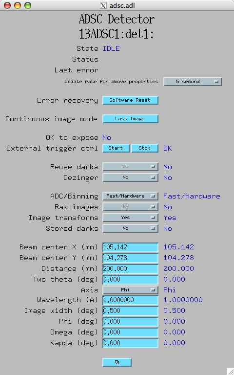
Driver Specific Values and Settings
This driver provides status values and settings in addition to what is provided
by areaDetector base
. They are listed here according to their label
in the driver specific MEDM GUI and their EPICS PV name in the EPICS PV driver interface.
A screenshot of the driver specific MEDM GUI can be seen in the
Screenshots section.
Detector Condition
- State, $(P)$(R)ADSCState
-
State of the detector reported by the ADSC control library.
- Status, $(P)$(R)ADSCStatus
-
Status message reported by the ADSC control library.
- Last error, $(P)$(R)ADSCLastError
-
Last error message reported by the ADSC control library.
- Update rate for above properties, $(P)$(R)ADSCReadConditn.SCAN
-
How frequently to update the above properties.
Detector Error Recovery
- Software Reset, $(P)$(R)ADSCSoftReset
-
Performs a software reset. Aborts any current operation, clears status and error
messages, and sets detector state to Idle.
Detector Continuous Image Mode
- Last Image, $(P)$(R)ADSCLastImage
-
Signals that the next exposure is the last image when in Continuous image
mode.
Detector External Software Trigger
- OK to expose, $(P)$(R)ExSwTrOkToExp
-
When in Ext. Software trigger mode, indicates whether it is OK to start
an image exposure.
- Start, Stop, $(P)$(R)ExSwTrCtl
-
When in Ext. Software trigger mode, set to 1 to start an exposure,
and set to 0 to stop it.
- $(P)$(R)ExSwTrCtlRsp
-
When in Ext. Software trigger mode, will be Start, Stop,
OK, or Again. See Trigger Modes section
for more about how this property will behave.
Driver Parameters
- Reuse darks, $(P)$(R)ADSCReusDrk
-
Reuse dark images when possible. This is useful to avoid wasting time acquiring
dark images when previously acquired dark images are available and can be reused.
- Dezinger, $(P)$(R)ADSCDezingr
-
Acquire
dezingered
images.
Detector Hardware Parameters
- ADC/Binning, $(P)$(R)ADSCAdc
-
For Q4 and Q4r detectors, controls whether to use Fast or Slow
ADC. For all other detectors, controls whether to use Hardware or Software
binning.
- Raw images, $(P)$(R)ADSCRaw
-
Write raw images.
- Image transforms, $(P)$(R)ADSCImXform
-
Perform image transformations.
- Stored darks, $(P)$(R)ADSCStrDrks
-
Use stored dark images. If set to Yes, stored dark images are assumed to
have been installed by ADSC and should be used.
Detector File Parameters
- Beam center X, $(P)$(R)ADSCBeamX
-
Beam center in the X dimension.
- Beam center Y, $(P)$(R)ADSCBeamY
-
Beam center in the Y dimension.
- Distance, $(P)$(R)ADSCDistnce
-
Detector distance.
- Two theta, $(P)$(R)ADSC2Theta
-
Detector 2θ angle.
- Axis, $(P)$(R)ADSCAxis
-
Crystal rotation axis.
- Wavelength, $(P)$(R)ADSCWavelen
-
X-ray wavelength.
- Image width, $(P)$(R)ADSCImWidth
-
Crystal rotation during exposure.
- Phi, $(P)$(R)ADSCPhi
-
Phi position at start of exposure.
- Omega, $(P)$(R)ADSCOmega
-
Omega position at start of exposure.
- Kappa, $(P)$(R)ADSCKappa
-
Kappa position at start of exposure.
Screenshots
Unsupported areaDetector base
Features
- Shutter control
- Collect: number of exposures per image
- File: save file
- File: read file
- File: format
- File: auto save (always Yes)
- Readout: image region of interest
- Readout: reverse image
- Readout: gain
- Readout: data type (always UInt16)
- Image frame callbacks
Limitations
- Only one ADSC detector may be controlled with this driver per OS process. If this
driver is being used in an IOC, this means only one ADSC detector may be controlled
with this driver per IOC. This is a limitation of the underlying ADSC control library
which does not support more than one detector per OS process.
- Acquiring
dezingered
images is not supported. This is a limitation of the
underlying ADSC control library which has a bug preventing it from working correctly.
- Software reset does not work. This is a limitation of the underlying
ADSC control library which has a bug preventing it from working correctly. It would
be great if, after an error, performing a software reset would allow a new acquisition
to proceed normally. Currently, the recovery solution often is to restart the control
software.