Generated on August 20, 2005 by Guoyin Shen
Last modified -------- by --------
A. Operations of 13-ID-D angle dispersive diffraction with DAC
A.1 Control interfacesB. Operations of 13-ID-D Laser Heating System
Pre-alignment of laser heating path with x-ray
Getting ready
Mounting DAC
Alignment of laser heating optics with x-ray
Turning on lasers
Adjusting the laser power
Feed back system
Data logger
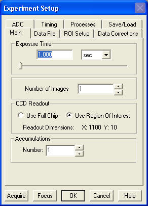
Winspec/32 setup
Winvew/32 setup
Temperature measurement software
Monitor setup
A. 1. Control interfaces
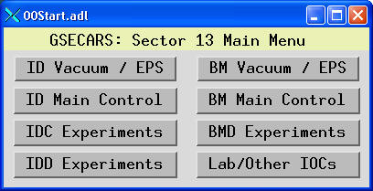
Click the shortcut MEDM at the desk top, you will have a MEDM window:
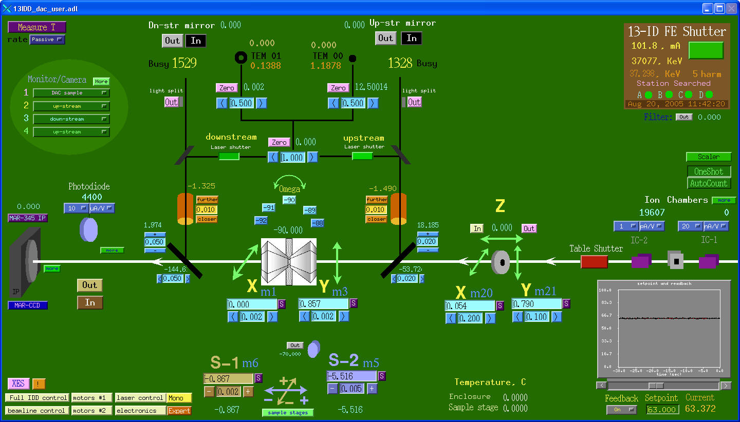
Click IDD Experiments > 13 IDD DAC
![]() , you will have the
main control window for DAC experiments at 13ID-D.
, you will have the
main control window for DAC experiments at 13ID-D.
Click the shortcut
IDL 6.0 at the desk top, you will have an IDL window: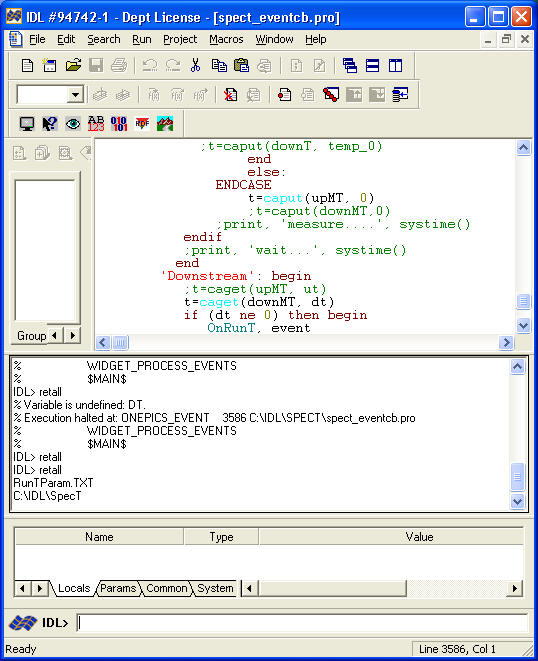
Under File>Preferences>Path, make sure the following setup:
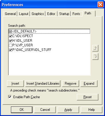
Under File>Preferences>Startup, setup the desired working directory:
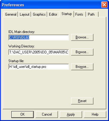
Click OK.
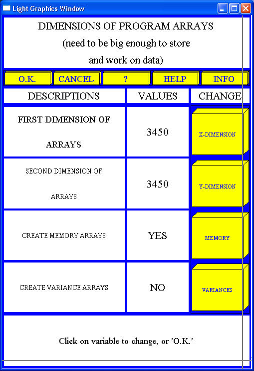
Click the shortcut Fit2D at the desktop, you will have a window:
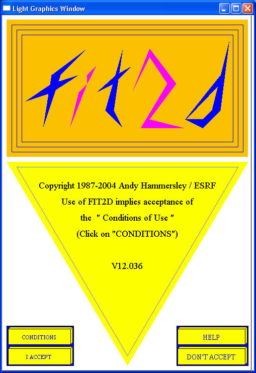
Click "I ACCEPT", then make sure to put the right dimensions of arrays.
Fit2D is a well documented software. You may get instructions from: http://www.esrf.fr/computing/scientific/FIT2D/
A. 2. Operations of ADX 13IDD-DAC
X-ray beam is pre-aligned to the rotation center of the sample stage. Therefore, we will start with checking the rotation center first. Then we will make sure that the x-ray beam is focused at the center. This process is made with the help of a cross hair.
· Move stages X, Y, S1, S2,
and Omega all to 0 (zero). For Omega stage, you may need an IDL window for
rotation. In the IDL command line, type "rotate_omega,
degree". Note that the degree number is always relative, with positive
number in clockwise direction if you look down.
·
Put a cross hair on the DAC setup.
·
Move microscope "IN" in the main control window.
You should see the cross in the monitor (see monitor setup). If you do not see
the cross hair, contact beam-line staff.
·
Rotate Omega -180 degrees
("rotate_omega, -180, psw=1" in IDL). The cross hair should stay at the center. If not, contact beam-line staff.
·
Move the microscope away.
·
Rotate Omega 90 degrees
("rotate_omega, 90" in IDL).
·
Scan clean-up slits first (see
Scan for setup).
·
Scan the cross hair. The cross hair should be close
to the zero positions of all stages within 20 um. If not, contact beam-line
staff.
Detector calibration is made by a couple of standard materials (CeO2, Si). Then by using the build-in features in Fit2D, the tilt and sample-detector distance can be determined. The x-ray energy is calibrated independently, by scanning an absorption edge of a particular element, which is usually done by beam-line staff. Contact beam-line staff for more information (accuracy, etc) about the x-ray energy.
· Move the clean-up slits
"OUT".
· Rotate Omega to 0 (zero) position (use
IDL).
· Put the holder with CeO2
standard. Under IDL command line, type "item, 'ceo2'
".
· Move microscope "IN". You
should see the CeO2 standard. Small adjustment maybe needed.
· Move microscope "OUT".
· Rotate Omega -90 degrees.
·
Move the clean-up slits "IN".
· Scan clean-up slits.
(refer to Scan)
· Get detector ready
(refer to Detectors). If IP
is used. Erase the IP before taking the standard exposure. Typically 1 second is
enough for CeO2.
· Use Fit2D for imaging
loading and detector calibration.
Now the system is ready for mounting your sample. For checking starting materials or quenched samples, there are special holders for that. Contact beam-line staff for those holders. The following is for DAC sample setup. Please note: if you are a new user, always discuss with beam line staff first for appropriate holders.
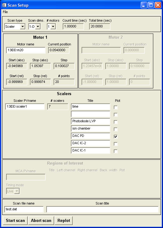
scan type
: scaler for scaler detectors (e.g., photodiode); roi for multi-channel detectors (e.g., MCA)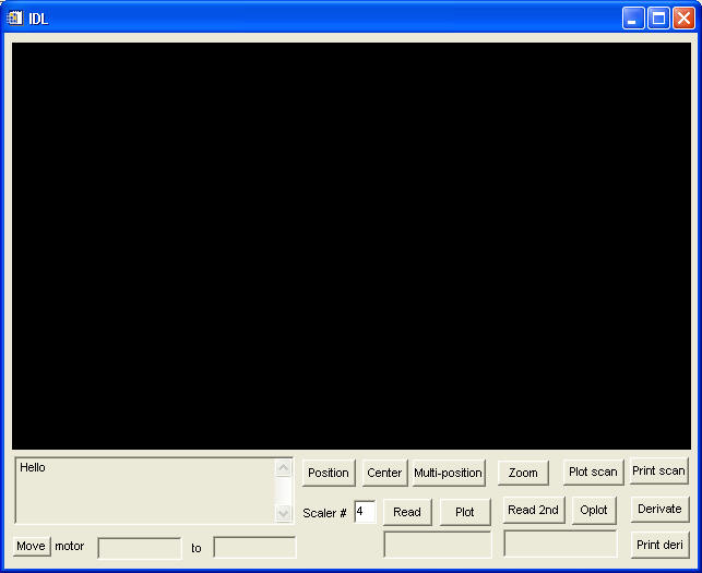
Used for scanning any positioners (a motor, a compound motor, or anything that has a PV name and can be controlled to "change") while watching any detectors (time, intensity of the photo diode, ROIs in the MCA, or anything that can be measured).
Scan parameter window
In the main DAC window, click FULL IDD CONTROL (lower-left corner), go to SCAN > scan2 (scan1 is usually used by LVP people)
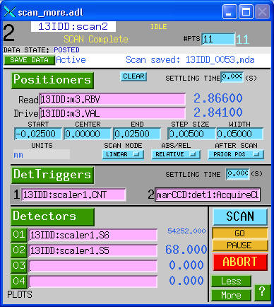
· For single motor scan,
just fill in the PV names under positioners.
· For multiple motor scan,
click the button "Positioners", which allows
you to enter up to four positioners for each scan.
· PV names under
Detector trigger are used for trigging
detectors. The example shown is for scaler1 in 13ID-D and MARCCD.
· PV names under Detectors
are those that you want to be recorded for a scan. Put the desired names there.
Data can be plotted by clicking the numbers of the corresponding detectors
 .
.
MAR-IP3450
The MAR-IP
is controlled by a computer named "mini"
To start MAR-IP control interface, just type
"MAR345" in a terminal window.
MAR-CCD
Currently, a MAR-CCD from
APS detector pool is used. The detector comes with a computer.
MAR-CCD can be controlled by EPICS.
The setup is done by beam-line staff.
Fuji BAS2500
Fuji BAS2500 is an off-line reader. Two sizes of imaging plate are available. One is 20x25 cm^2; the other is 20x40 cm^2.
Troubleshooting
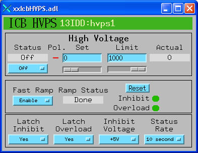
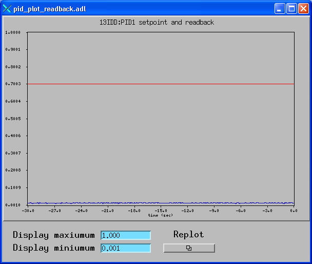
· Is the main shutter open? If yes, check the window at the lower-right corner of the DAC window. If current reading is 0(zero), contact beam-line staff.
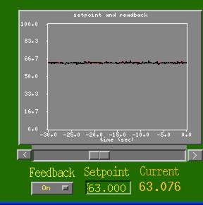
· If Current reading changes over time as shown below, this means that the Setpoint is a little too high for the feedback to keep the top number. Reset the Setpoint number (5% below the maximum).

·
If you have a good reading from Current, but no
x-ray beam from photodiode, then check the following:
· Is the table-top shutter OPEN?
· Is clean-up slit at the right position?
· Is the photodiode IN?
· If yes to all above, but still no beam, contact
beam-line staff.
Operations of the 13-ID-D Laser Heating System
Alignment of laser heating path with x-rayThis procedure is done normally before experiment. Only do this when problems observed or to confirm the alignment.
Alignment of laser heating optics with x-ray beam
Lasers
Interlock (user mode only)
The feed back system monitors the thermal radiation from the heated spot at the downstream side and feeds back to the waveplate-controlled power.
· From the main MEDM window, go to Laser control > Laser control slow. Set the PV names as shown.
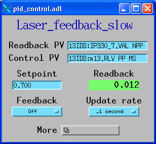
· Go to More and click Plot control value:
· Read the
Readback value, and put the Setpoint
with a close value to the Readback.
· Then turn ON the
Feadback.
· Change the Setpoint
value for increase/decrease the sample temperature.
Epics Logger (data logger software)
The experimental parameters can be lively recorded by using a data logger program in IDL.
·
In an open IDL window, type: epics_logger
· From File, you select the input data file and
the output file. There is a file P:\dac_user\data_logger\laser_logger.dat
for input data file. Using this file will record the time and date, the
setpoint, the readback, the upstream temperature, the downstream temperature,
and the photodiode output for the laser power. You may create your own data file for your needs. Basically any parameter
variables (motor positions, slit width, ring current etc) can be recorded. Of
course, an output file should be set for storing the data.
· Update
time in the epics logger should be set (typically 1 sceond).

Temperature is measured by collecting the thermal radiation from a hot spot. The radiation signal is fitted to the Planck law and the fitting parameters give temperature values. The control is done by a GUI written in IDL. This GUI talks to Winspec32 and calculates temperatures. So file names have to be specified first in Winspec32. Refer to Winspec32 for the setup.
· Open a new IDL window.
·
In the command line, type: spect

· Click Setup Parameters ..., it will show:
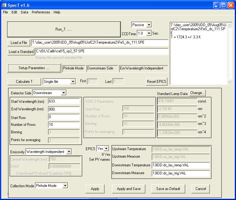
· Make sure that Detector side and other
parameters are correctly selected. Click Apply (or others as desired).
· It
is essential to load a Standard before a temperature calculation may be
performed.
· If
the GUI freezes, go to the IDL window which opens the SpecT, and type "retall".
·
If EPICS control is set to "yes", then temperature measurement can be triggered
by "Measure T" in the upper-left corner in the DAC main window. The calculated
temperatures are also displayed in the main window.
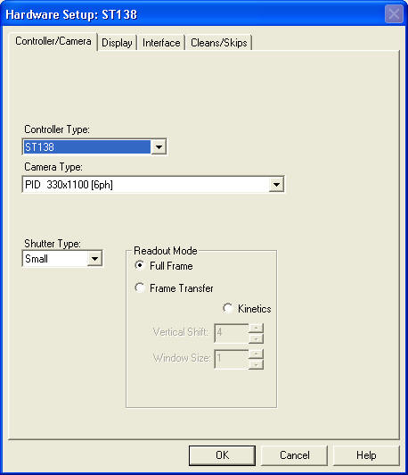
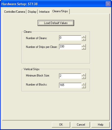
Under Setup>Hardwares
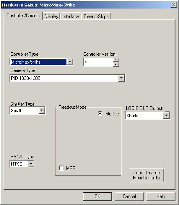
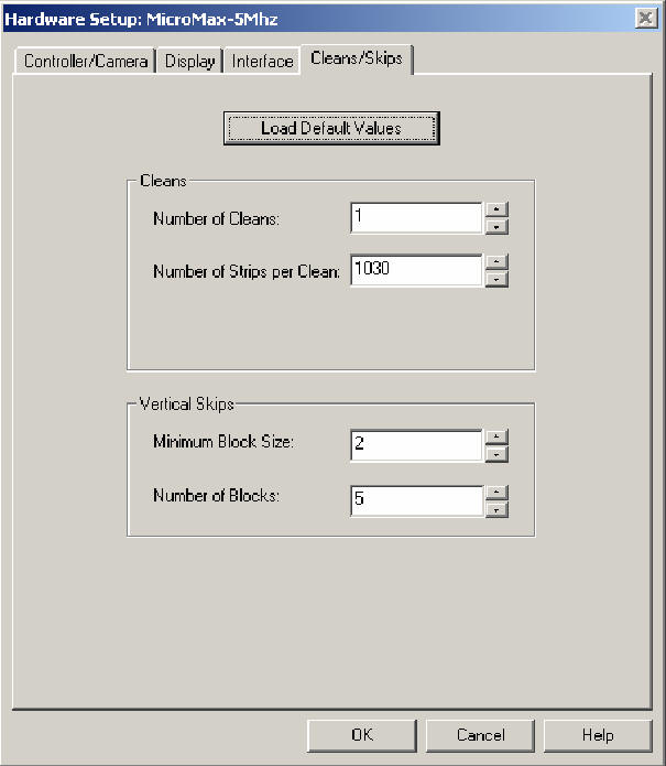
Click OK. Winview is ready for taking data
There are four monitors in the 13ID-D, two outside the hutch and two inside. Those monitors can display video images from any source controlled by EPICS. Control buttons in the upper-left side in the main control window can be used for those operations.